Liquid crystal display device

Active Publication Date: 2009-08-13
PANASONIC LIQUID CRYSTAL DISPLAY CO LTD +1
View PDF4 Cites 91 Cited by
  • Summary
  • Abstract
  • Description
  • Claims
  • Application Information

AI Technical Summary

Benefits of technology

[0019]Accordingly, the present invention is made in order to solve the above described problems, and an object thereof is to provide a liquid crystal display device capable of curving a display surface of a liquid crystal display panel by preventing the liquid crystal display panel from being damaged due to bending of a light-transmissive substrate.
[0020]And, another object of the present invention is to provide a liquid crystal display device having a liquid crystal display panel capable of maintaining a stable curved state for a long time after being curved and finished, and capable of improving reliability thereof.
[0021]In order to achieve the above described objects, a liquid crystal display device according to the present invention comprises: a liquid crystal display panel having a liquid crystal layer sealed between a pair of light-transmissive substrates each having a pixel formation electrode formed on an inner surface thereof and having a curved shape formed by assembling positive and negative curvatures with respect to one direction; a backlight mounted on a rear surface of the liquid crystal display panel along the curved shape of the liquid crystal display panel and having at least one light emission device irradiating illumination light toward the rear surface of the liquid crystal display panel; and

Problems solved by technology

However, most plastic has heat-proof temperature equal to or lower than about 200° C. and it is not tolerant to a process at about 350° C. to 600° C. required for manufacturing of a thin film transistor using amorphous silicon and polysilicon.
Therefore, formation of an active matrix type substrate including a thin film transistor having high-performance and high-precision on a plastic substrate is extremely

Method used


Image

  • Liquid crystal display device
  • Liquid crystal display device
  • Liquid crystal display device

Examples


embodiment 1

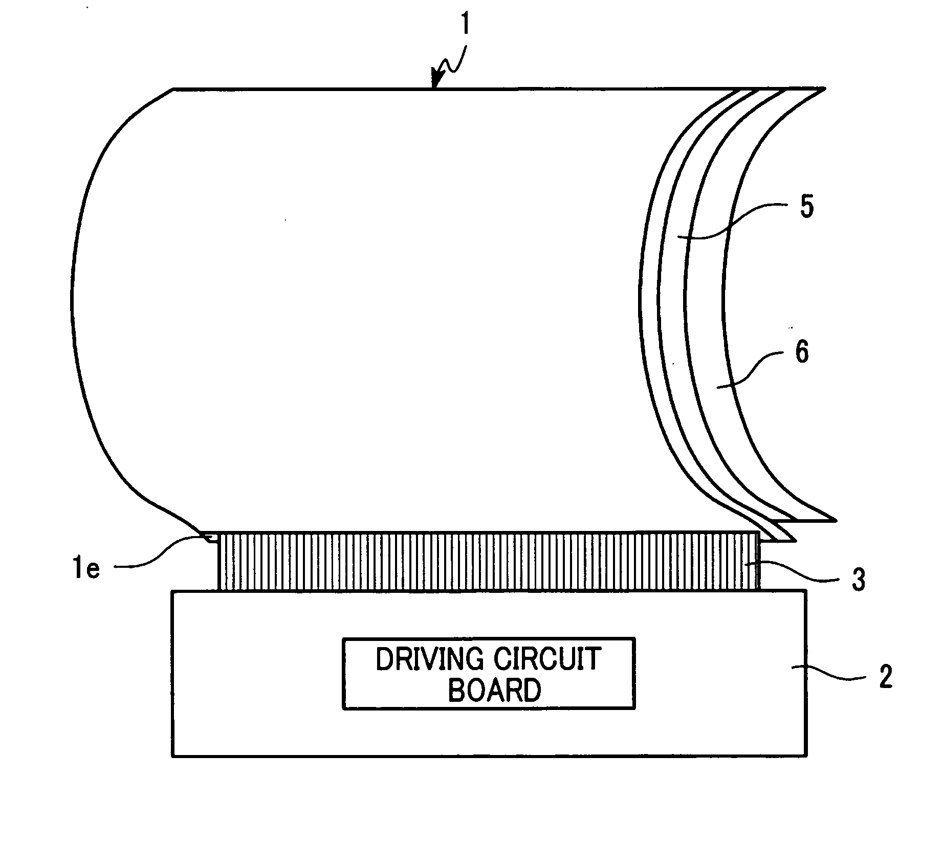
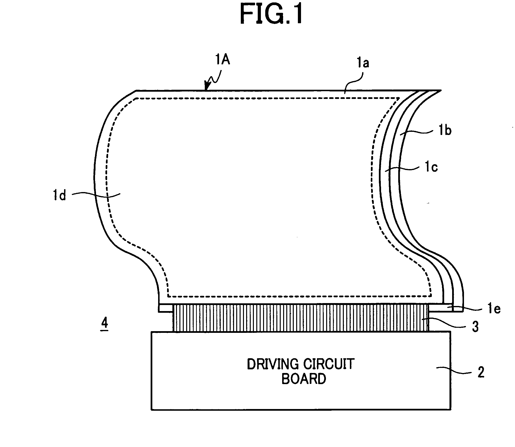
[0039]FIG. 1 is a schematic diagram showing structure of a liquid crystal display module to explain a liquid crystal display device according to one embodiment of the present invention. In FIG. 1, a liquid crystal display panel 1A is formed by sealing a liquid crystal layer in a space between a pair of light transmissive glass substrates 1a, 1b each having a pixel selection electrode formed on an inner surface thereof and sealing opposed peripheral portions thereof using a sealing member 1c. And, structure is provided, in which orientation of the liquid crystal is changed according to an electric field applied to the liquid crystal from the pixel selection electrode, source light irradiated from a backlight mounted on a rear surface side of the liquid crystal display panel 1A is polarized by about 90 degrees in the liquid crystal layer and then passed through a polarizer, and therefore, a latent electron image can be seen as a visible image on a display surface 1d.

[0040]And, in the...

embodiment 2

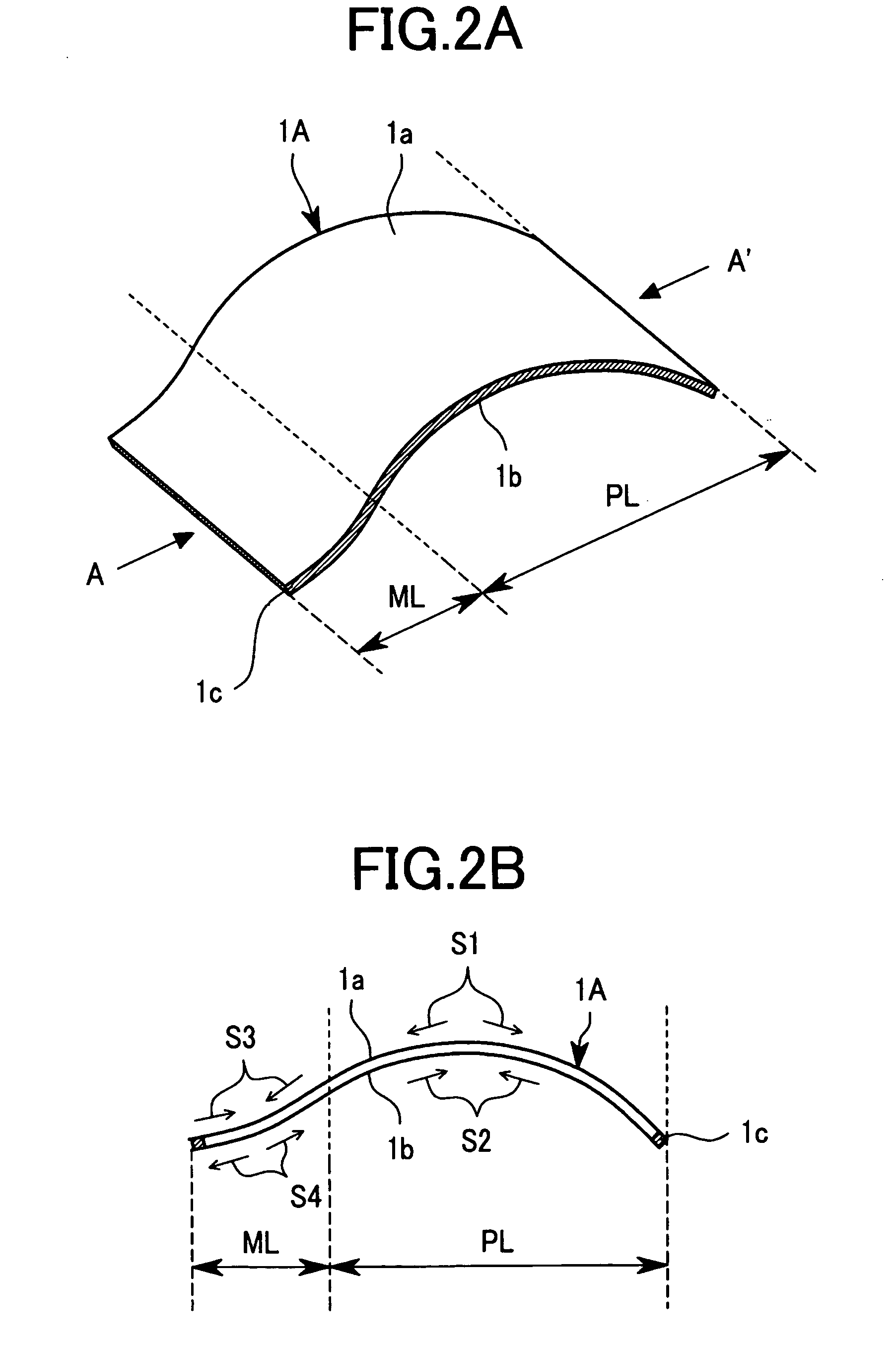
[0050]FIGS. 6A and 6b are diagrams showing a liquid crystal display panel to explain structure of a liquid crystal display device according to one embodiment of the present invention. FIG. 6A is a perspective view and FIG. 6B is a cross sectional view along a line A-A′ shown in FIG. 6A. The liquid crystal display panel 1B shown in FIG. 6 is formed to have freely-bendable flexibility by integrally assembling a negative (concave) curved portion ML, a positive (convex) curved portion PL and another negative (concave) curved portion ML with respect to one direction. That is, the liquid crystal display panel 1 is formed to have opposite glass curved directions (curvatures) between areas in the vicinities of both end portions of the liquid crystal display panel 1 and other area thereof (an area in the vicinity of center of the panel).

[0051]And, on a rear surface side of this liquid crystal display panel 1B, although not shown in the diagram, a resin member and a suspend light type backlig...


PUM

PropertyMeasurementUnit
Thicknessaaaaaaaaaa
Lightaaaaaaaaaa

Abstract

A liquid crystal display device preventing a liquid crystal display panel from damage by bending of a light-transmissive substrate and capable of curving a display surface of the panel is provided. The liquid crystal display device comprising: a liquid crystal display panel having a liquid crystal layer sealed between a pair of light-transmissive substrates having pixel formation electrodes on inner surfaces thereof, and formed by assembling positive and negative curved surfaces with respect to one direction; a backlight mounted on a rear surface of the panel along a curved shape of the panel and having at least one light emission device irradiating illumination light toward the rear surface; and a resin member held in a space between peripheral portions where the panel is opposed to the backlight, and fixing and holding a curved state, is provided. Distortion of the light transmissive glass substrates by bending of the panel is eased.

Description

CROSS-REFERENCE TO RELATED APPLICATION[0001]The present application claims priority from Japanese application JP 2007-208345 filed on Aug. 9, 2007, the content of which is hereby incorporated by reference into this application.BACKGROUND OF THE INVENTION[0002]1. Field of the Invention[0003]The present invention relates to a liquid crystal display device for use in a television, a personal computer and the like, for example, in particular, to a liquid crystal display device having a curved liquid crystal display panel, and in detail, to curved structure of a liquid crystal display panel.[0004]2. Description of the Related Art[0005]A liquid crystal display panel forming a liquid crystal display device is basically an image display device having structure in which a liquid crystal layer is sealed between first and second substrates preferably made of glass substrates and utilizing nature that orientation of liquid crystal changes according to an electric field applied to the liquid cry...

Claims


Application Information

Patent Timeline
IPC IPC(8): G02F1/1333G02F1/13357
CPCG02F1/1333G02F1/133604G09F9/35G02F2201/56G02F2001/133302B32B17/10G02F1/133302
Inventor SASAKI, SUSUMUAZUMA, HITOSHIEBINE, TAKAOYAGUCHI, TOMIOUCHINO, SHOICHIIWATA, AKIKO
Owner PANASONIC LIQUID CRYSTAL DISPLAY CO LTD
Why Eureka
Try Eureka