
Distortion Control Device and Method

a technology of distortion control and control device, applied in the direction of gain control, digital transmission, baseband system details, etc., can solve the problem that the hsupa cannot meet the adjacent channel leakage power standard, and achieve the effect of preventing an increase in the adjacent channel leakage power

Inactive Publication Date: 2009-08-13
LENOVO INNOVATIONS LTD HONG KONG
View PDF8 Cites 12 Cited by
  • Summary
  • Abstract
  • Description
  • Claims
  • Application Information

AI Technical Summary

Benefits of technology

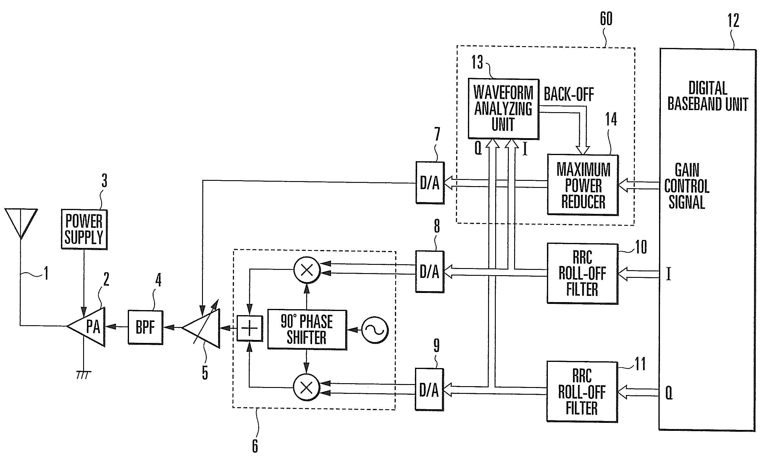
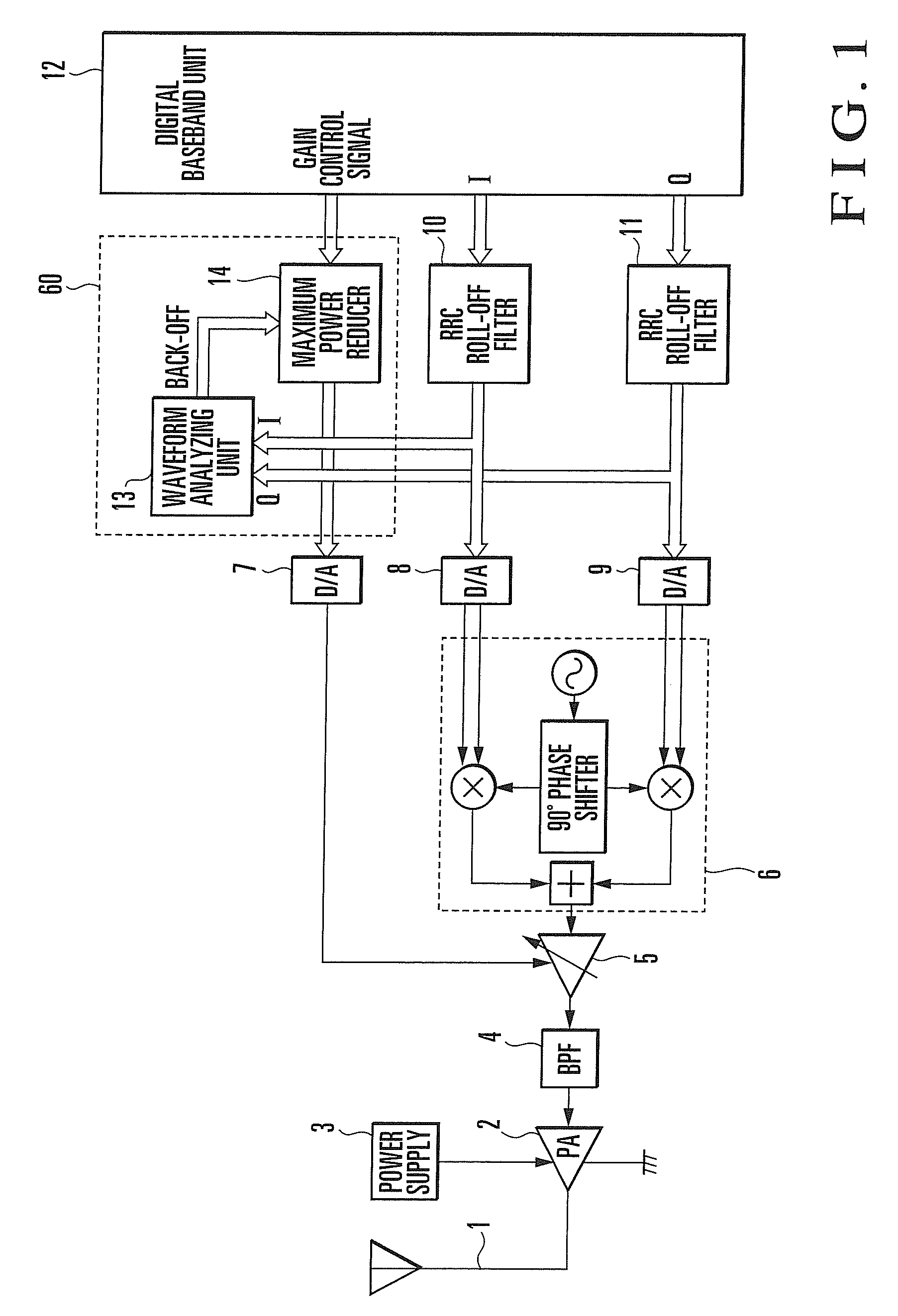
[0018]According to the present invention, since the estimated value of a back-off value is calculated by analyzing the waveform of a baseband signal, there is no need to generate a table in advance by calculating a back-off value in advance for each combination of code channels. The present invention can therefore be applied to even a case in which the number of code channels greatly increases, and can effectively prevent an increase in adjacent channel leakage power due to a signal obtained by multiplexing these code channels.

Problems solved by technology

Compared with R99, therefore, HSUPA cannot meet the adjacent channel leakage power standard when amplification is performed by the same amplifier, because a large distortion occurs at an amplitude peak, unless the transmission power is decreased.

Method used


Image

  • Distortion Control Device and Method
  • Distortion Control Device and Method
  • Distortion Control Device and Method

Examples


Embodiment Construction

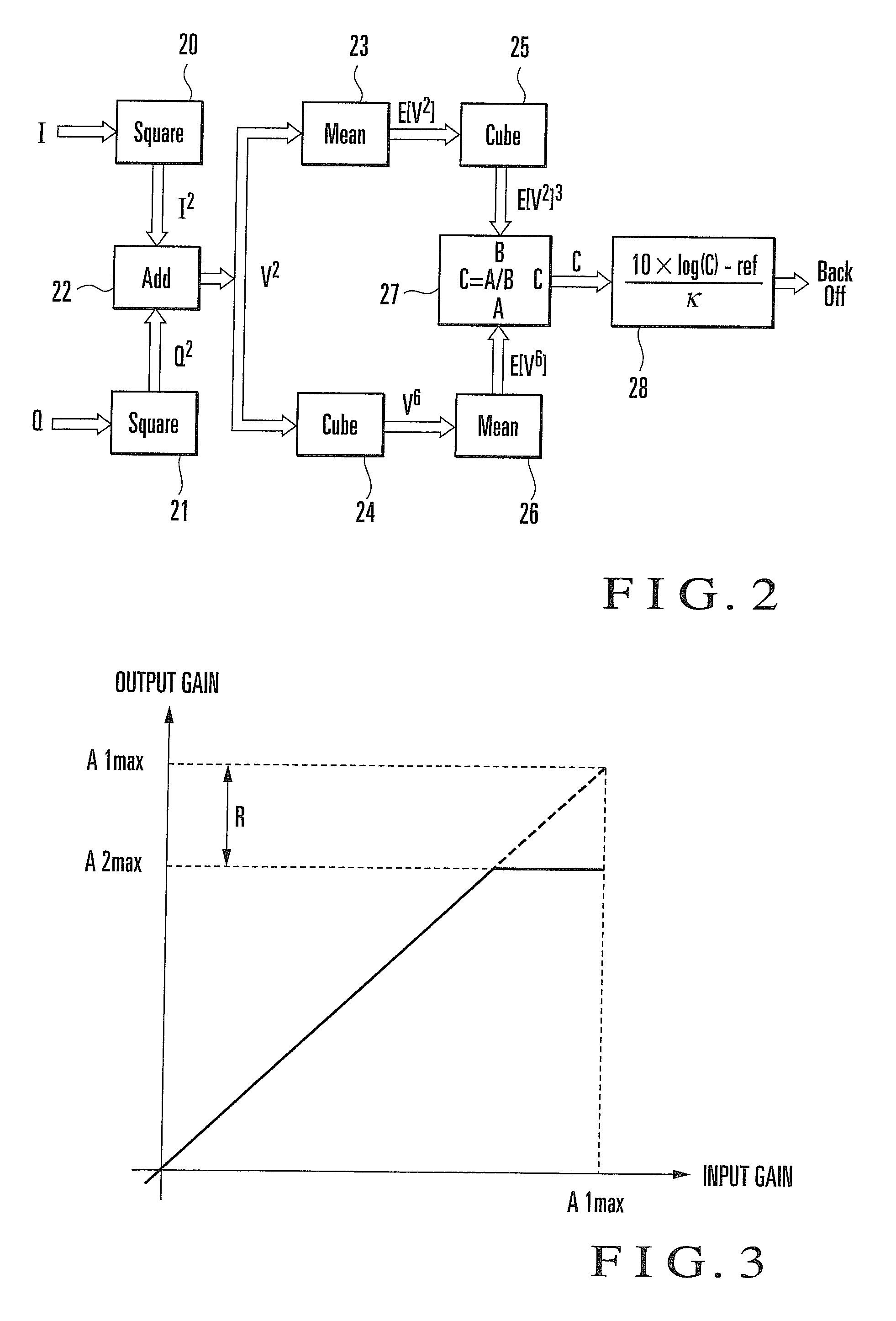
[0033]The principle of the exemplary embodiments of the present invention will be described first. The exemplary embodiment of the present invention uses a technique called Cubic Metric (to be simply referred to as CM) as a method using no table like that described above. The following is a calculation method based on this CM method.

[0034]A transmission waveform x(t) is given by

x(t)=V(t)·cos {ωc·t+φ(t)}

where V(t) is an amplitude, and φ(t) is a phase. In CM, only an amplitude is used.

[0035]First of all, RCM (Raw Cubic Metric) is defined.

RCM=20·log10 {rms[V3norm(t)]}

where Vnorm(t) is given by

Vnorm(t)=|V(t)| / rms[V(t)]

As a consequence, RCM is given by

RCM=20·log10{rms[V(t)3rms[V(t)]3]}=20·log10{rms[rms[V(t)3]rms[V(t)]3]}=10·log10{V(t)6_V(t)2_3}[equation1]

[0036]The numerator in the log is the sextic moment of an amplitude probability density function, and the denominator is the cube of average power (quadratic moment). Therefore, RCM is a variable determined when at least an amplitude pro...


PUM


Abstract

This invention includes a waveform analyzing means (13) for calculating an estimated value of a back-off value required by a power amplifier (2), which amplifies a high-frequency signal generated from a baseband signal (I, Q) to a predetermined transmission power, by analyzing the waveform of the baseband signal (I, Q), and a control means (14) for controlling at least one of the amplitude of high-frequency power input to the power amplifier (2) and the supply power of the power amplifier (2) on the basis of the estimated value. The invention calculates the estimated value of a back-off value by analyzing the waveform of a baseband in this manner, and hence need not generate a table in advance by calculating a back-off value for each combination of code channels. The invention can therefore be applied to even a case in which the number of code channels greatly increases, and can effectively prevent an increase in adjacent channel leakage power due to a signal obtained by multiplexing these code channels.

Description

TECHNICAL FIELD[0001]The present invention relates to a distortion control device and method.BACKGROUND ART[0002]The transmission-side circuit arrangement of a mobile terminal apparatus based on a general W-CDMA scheme will be described with reference to FIG. 9. A baseband signal comprises an in-phase component (to be referred to as an I signal) and a quadrature component (to be referred to as a Q signal) in quadrature modulation. A digital baseband unit 112 generates this signal. RRC (Raised Root Cosine) roll-off filters 110 and 111 for waveform shaping band-limit the I and Q signals. The processing so far is digital signal processing.[0003]D / A converters 108 and 109 then respectively convert the I and Q signals into analog signals. A known quadrature modulator 106 performs quadrature modulation for a local signal with these analog signals. The high-frequency signal generated as a result of this operation is input to a variable gain amplifier (VGA) 105, which then amplifies it to a...

Claims


Application Information

Patent Timeline
IPC IPC(8): H04L25/03H04B1/707
CPCH03G3/004H03G3/3042H04B2201/70706H04B1/0475H03G3/3047
Inventor ICHIHARA, MASAKI
Owner LENOVO INNOVATIONS LTD HONG KONG
Learn More