Thermal Electric NOR Gate

a technology of thermal electric and gate, applied in the direction of logic circuits, logic circuits characterised by logic functions, pulse techniques, etc., can solve the problem of high insensitivity of devices, and achieve the effect of low energy consumption, low cost and high density circuits

Active Publication Date: 2009-08-20
MACOM CONNECTIVITY SOLUTIONS LLC
View PDF2 Cites 3 Cited by
  • Summary
  • Abstract
  • Description
  • Claims
  • Application Information

AI Technical Summary

Benefits of technology

[0008]A solid state NOR gate logic device is presented that requires no active semiconductor diodes, transistors, or vacuum tubes, and which can be configured into basic circuit blocks performing logic functions. The solid state NOR gate device can be fabricated without expensive semiconductor processing, is insensitive to contamination, and operates with a wide range of supply voltages, from volts down to the tens of millivolt range. The device is highly insensitive to ...

Problems solved by technology

The device is highly insensitive to ...

Method used


Image

  • Thermal Electric NOR Gate
  • Thermal Electric NOR Gate
  • Thermal Electric NOR Gate

Examples


Embodiment Construction

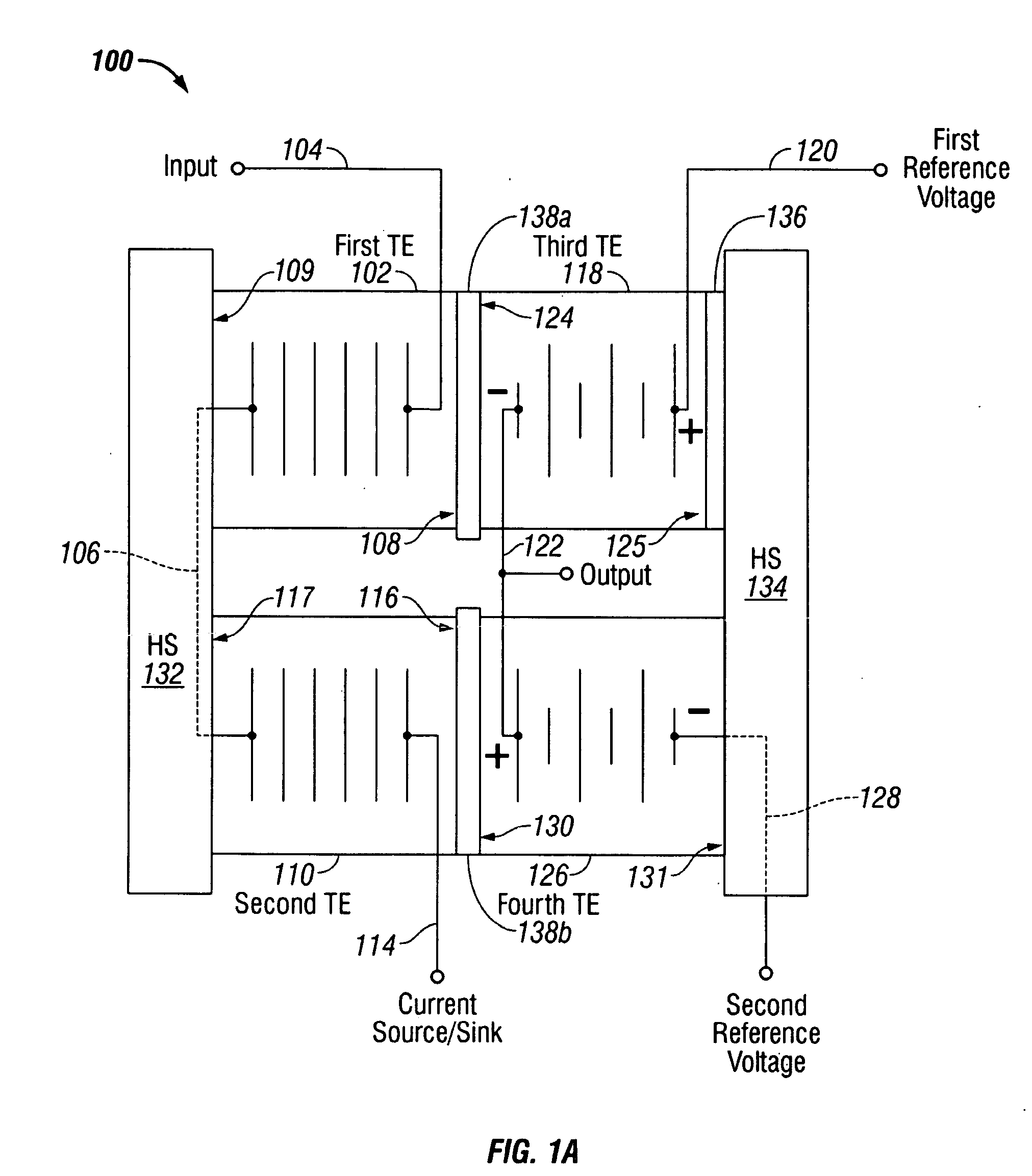
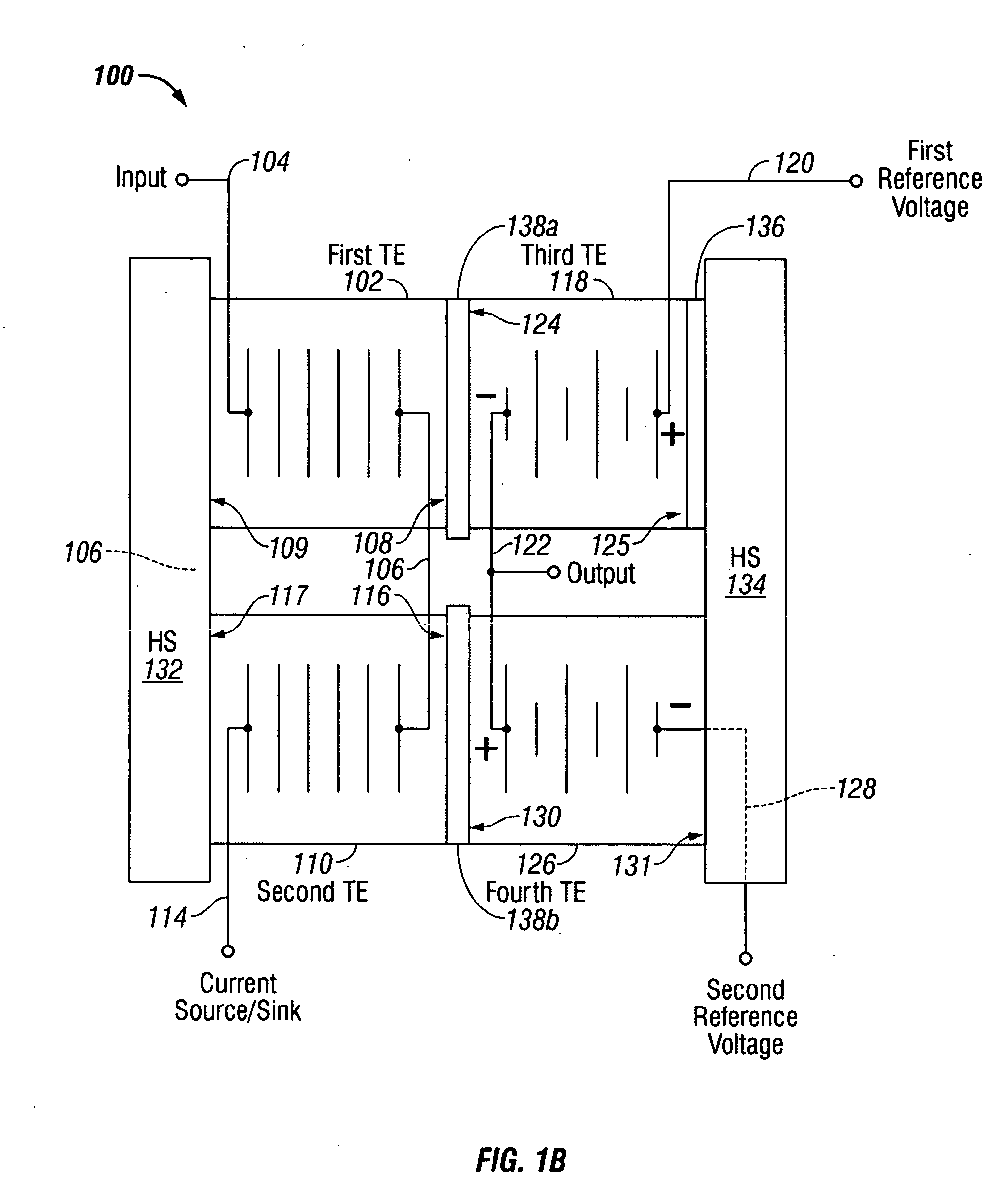
[0030]FIGS. 1A and 1B are schematic block diagrams of thermal electric binary logic circuits. FIG. 1A is an inverter and FIG. 1B is a non-inverter. The logic circuit 100 comprises a first thermal electric (TE) element 102 having a first electrical interface connected on line 104 to accept an input voltage representing an input logic state and a second electrical interface connected on line 106. The first TE element 102 has a thermal interface 108 to supply a first temperature responsive to the input voltage on line 104 and a second thermal interface 109. A second TE element 110 has a first electrical interface, electrically connected to the first TE second electrical interface on line 106, and a second electrical interface connected with line 114 to a current source / sink. The current source / sink reference on line 114 has an intermediate voltage, approximately midway between an input logic high voltage and an input logic low voltage. The second TE element 110 has a thermal interface ...


PUM


Abstract

A thermal electric (TE) binary NOR gate logic circuit is provided with a method for NOR logic gating. The method accepts a first input voltage representing an input binary logic state and generates a first thermal electric (TE) temperature in response to the first input voltage. A second input voltage is accepted representing an input binary logic state, and a second TE temperature is generated in response to the second input voltage. In response to the first and second TE temperatures, a NOR logic state output voltage is generated. More explicitly, a first control voltage is generated in response to the first TE temperature, and a second control voltage is generated in response to the second TE temperature. Then, a third TE temperature is generated in response to the first and second control voltages, which in turn generates the output voltage.

Description

RELATED APPLICATIONS[0001]This application is a Continuation-in-part of a pending patent application entitled, THERMAL ELECTRIC LOGIC CIRCUIT, invented by Joseph Patterson, Ser. No. 12 / 040,765, filed Feb. 29, 2008, Attorney Docket applied—251;[0002]which is a Continuation-in-part of a pending patent application entitled, SOLID STATE THERMAL ELECTRIC LOGIC, invented by Joseph Patterson, Ser. No. 12 / 032,549, filed Feb. 15, 2008, Attorney Docket applied—248. Both the above-mentioned applications are incorporated herein by reference.BACKGROUND OF THE INVENTION[0003]1. Field of the Invention[0004]This invention generally relates to binary logic circuitry and, more particularly, to a solid state NOR gate logic device made from thermal electric components instead of semiconductor transistors.[0005]2. Description of the Related Art[0006]Three-element (cathode / grid / plate) triode tubes and transistors are widely understood electronic devices used for signal processing and logic operations. It...

Claims


Application Information

Patent Timeline
IPC IPC(8): H03K19/20
CPCH03K19/02
Inventor PATTERSON, JOESPH MARTIN
Owner MACOM CONNECTIVITY SOLUTIONS LLC
Why Eureka
Try Eureka