
Flexible printed cable, head stack assembly with the same and manufacturing method thereof

Inactive Publication Date: 2009-08-20
SAE MAGNETICS (HK) LTD
View PDF7 Cites 20 Cited by
  • Summary
  • Abstract
  • Description
  • Claims
  • Application Information

AI Technical Summary

Benefits of technology

[0014]According to another embodiment of the HSA of the present invention, the first voltage pads and the corresponding second voltage pads are electrically connected with each other by electrical leads, laser welding, anisotropic conductive film, or electrical wire connection. Selectively, the first voltage pads and the corresponding second voltage pads are electrically connected with each other using golden balls, solder balls, silver epoxy balls, or solder paste. In addition, epoxy or resin is disposed between the first voltage pads and the second voltage pads to protect the electrical connection of the first voltage pads and the second voltage pads.

Problems solved by technology

However, before the test, all the micro-actuators of the HSA are electrically connected with the FPC and particularly all the electrical leads for controlling the micro-actuators at the tail portions of the flexible cables are connected to the common voltage end 133 and the common ground end 134 in parallel, so it is difficult to test all the micro-actuators' performance at the same time and difficult to judge whether every micro-actuator is eligible, thereby the productive efficiency is low.
However, the testing method can not be implemented to a HSA with a plurality of HGAs and a plurality of corresponding micro-actuators.
When the electric probes contact with any micro-actuator voltage trace and any micro-actuator ground trace, all the micro-actuators are parallelly connected to the testing system, so it is hard to judge which micro-actuator the test result belongs to and hard to judge which micro-actuators are eligible and which micro-actuators are not.

Method used


Image

  • Flexible printed cable, head stack assembly with the same and manufacturing method thereof
  • Flexible printed cable, head stack assembly with the same and manufacturing method thereof
  • Flexible printed cable, head stack assembly with the same and manufacturing method thereof

Examples


Embodiment Construction

[0046]Various preferred embodiments of the invention will now be described with reference to the figures, wherein like reference numerals designate similar parts throughout the various views.

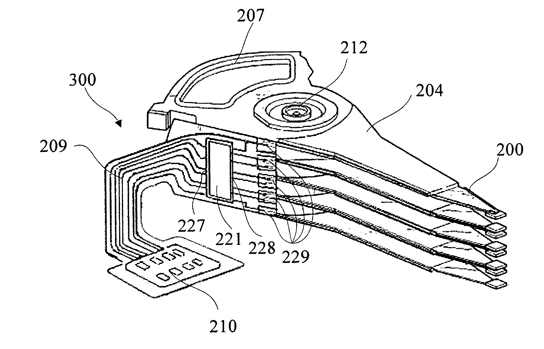
[0047]Firstly, embodiments of HSAs according to the present invention are described. As shown in FIG. 7, an HSA 300 according to one embodiment of the present invention includes a plurality of HGAs 200, such as five HGAs 200, a plurality of actuator arms 204 corresponding to the HGAs 200, a fantail voice coil 207 and a FPC 209 adapted to connect the HGAs with a printed circuit board (not shown) of a control system of a disk drive unit. The actuator arms 204 are stacked and connected with the fantail voice coil 207 by a secure means, such as a bearing 212, so as to stack the HGAs 200. The FPC 209 provides a connector 210 for connecting with the printed circuit board at one end thereof. The FPC 209 is connected to the control system by connecting the connector 210 with the printed circuit board. T...


PUM


Abstract

A HSA includes a plurality of HGAs and an FPC. The FPC includes a connector for connecting with a control system, a voltage trace and a ground trace. A common voltage end of the voltage trace has a plurality of first voltage pads and a plurality of second voltage pads arranged adjacent to the corresponding first voltage pads respectively and electrically isolated from the respective first voltage pads. Each of the second voltage pads connects with the micro-actuator of the corresponding HGA. A common ground end of the ground trace has a plurality of micro-actuator ground pads, each of which connects with a micro-actuator of the corresponding HGA. The second voltage pads and the corresponding first voltage pads are connected with each other after the micro-actuator are tested. The invention also discloses a manufacturing method of the HSA.

Description

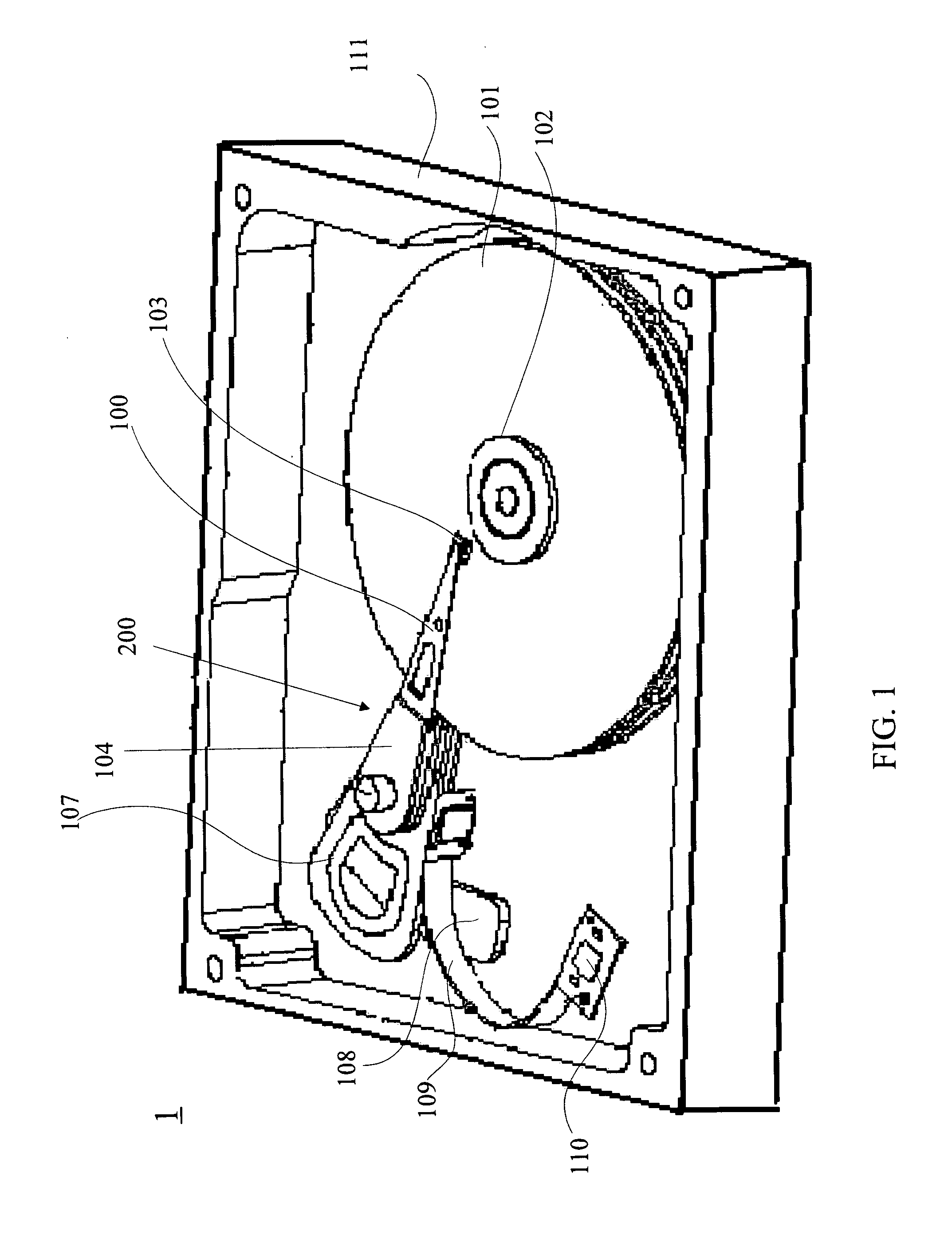
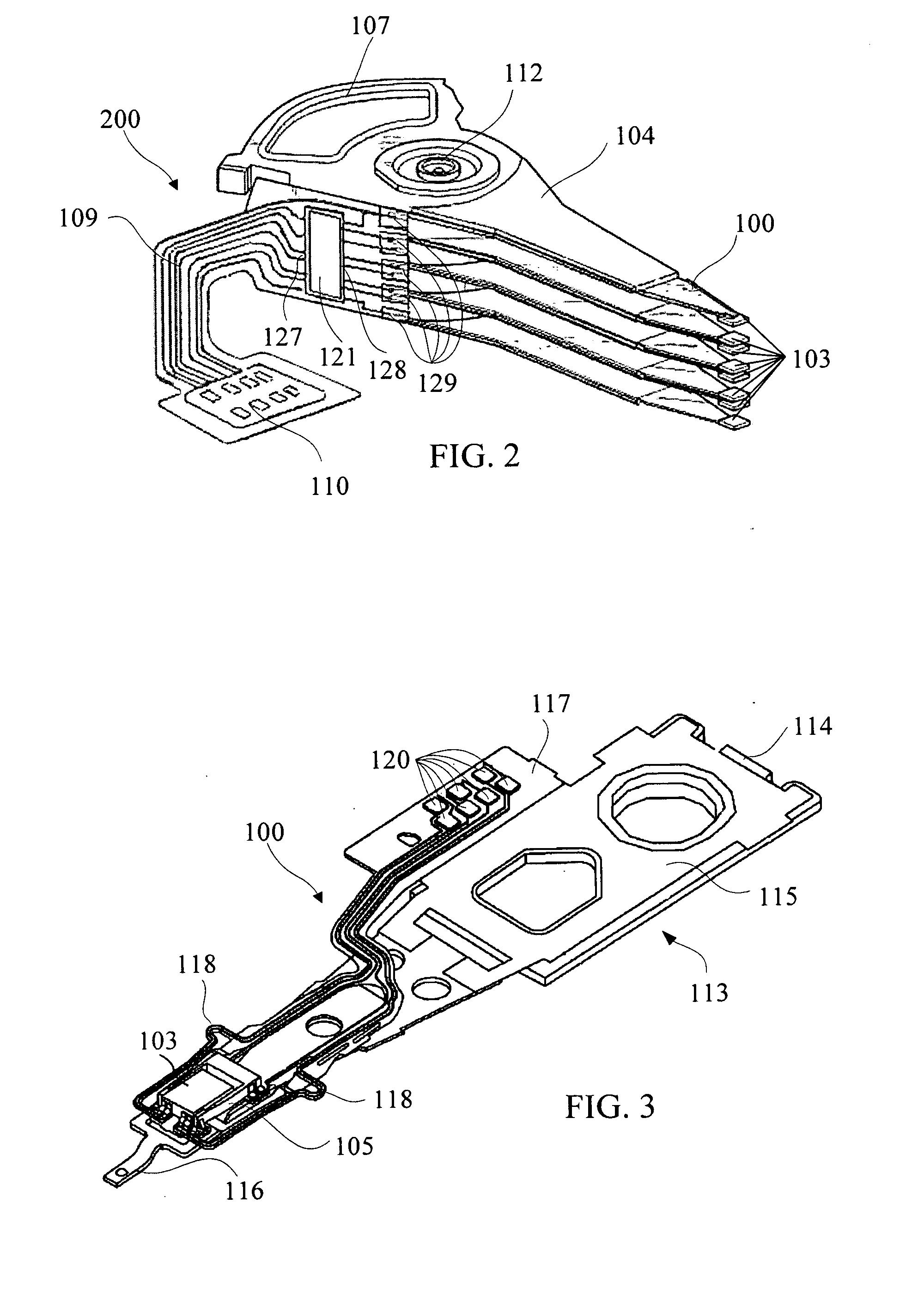
FIELD OF THE INVENTION[0001]The present invention relates to an information recording disk drive unit, and more particularly to a flexible printed cable (FPC) of the disk drive unit, a head stack assembly (HSA) with the FPC and its manufacturing method.BACKGROUND OF THE INVENTION[0002]Disk drives are information storage devices that use magnetic media to store data. FIG. 1 is a schematic view of a typical hard disk drive (HDD). As shown in FIG. 1, the HDD 1 includes at least one disk 101, a spindle motor 102 for spinning the disk 101, a voice coil motor (VCM) 108 and a head stack assembly (HSA) 200. The HSA 200 connects to a printed circuit board used for controlling the HSA and sliders through the FPC 109. All the components above-mentioned are located in a housing 111 of the HDD.[0003]FIG. 2 illustrates the detailed structure of the HSA 200 shown in FIG. 1. Referring to FIGS. 1-2, the HSA 200 includes a plurality of head gimbal assemblies (HGA) 100 formed at one end thereof. One e...

Claims


Application Information

Patent Timeline
IPC IPC(8): G11B21/16
CPCG11B5/4846G11B5/4853G11B5/486H05K2203/173H05K1/0293H05K1/0393H05K2203/162H05K1/0268
Inventor YAO, MINGGAO
Owner SAE MAGNETICS (HK) LTD
Learn More