A factor limiting the development of many of the discovered offshore hydrocarbon deposits, particularly
crude oil,
natural gas, and associated
natural gas liquids, is the cost to install and maintain equipment and facilities to produce the hydrocarbons.
Offshore drilling and production platforms and subsea production equipment installations require sizeable investments.
Although large, lengthy flowlines are significantly less expensive that new offshore production platforms, such flowlines may limit the fluid
production rate from a given well.
One of the more significant factors limiting the amount of fluid a given oil or gas well may produce is the amount of
back pressure exerted at the
wellhead by facilities downstream of the
wellhead.
When the
wellhead flowing pressure can be reduced, a typical well can produce more fluid from a given reservoir, which leads to a longer field production life and more oil and gas
recovery.
For example, flowlines from subsea wellheads to separation facilities may in some cases be several miles long which can result in significant friction losses caused by the turbulent, multiphase fluid flow in the flowlines.
Such friction losses result in an increase in pressure required to move a given amount of fluid through a flowline.
This
pressure increase, when added to the operating pressures of facilities downstream of the wellhead, may significantly increase the wellhead flowing pressure.
(Such changes in elevation cause an increased fluid head, i.e. a column of fluid, in a flowline which increases the wellhead flowing pressure and significantly reduces fluid production.)
Such two-phase flow results in increased pressure losses compared to
single phase flow in a flowline, such as where gases are produced through one flowline and liquids (oil and water) are produced through another flowline.
A separate, but related, problem may occur in a two-phase flow when large volumes of liquids accumulate in a flowline and upon accumulation of adequate pressure, are pushed forward and produced in a very short period of time as large slugs of liquids.
Liquids produced during a slugging event can overwhelm the
fluid handling capabilities of equipment employed on an offshore platform or facility as well as create high back pressures on a well.
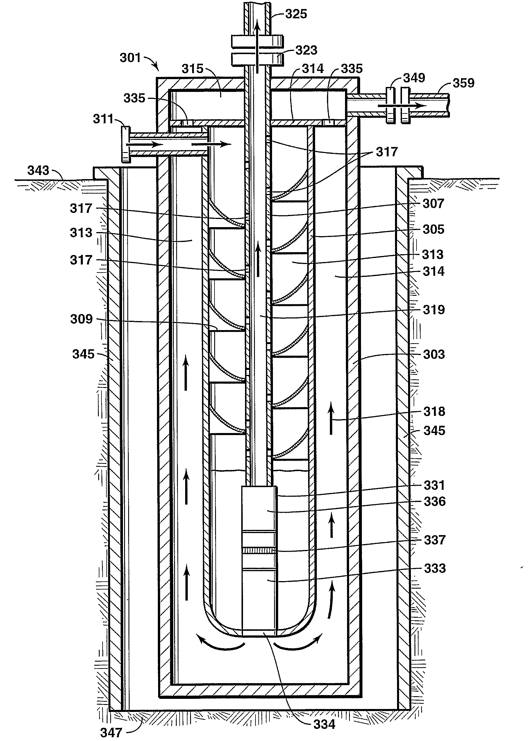
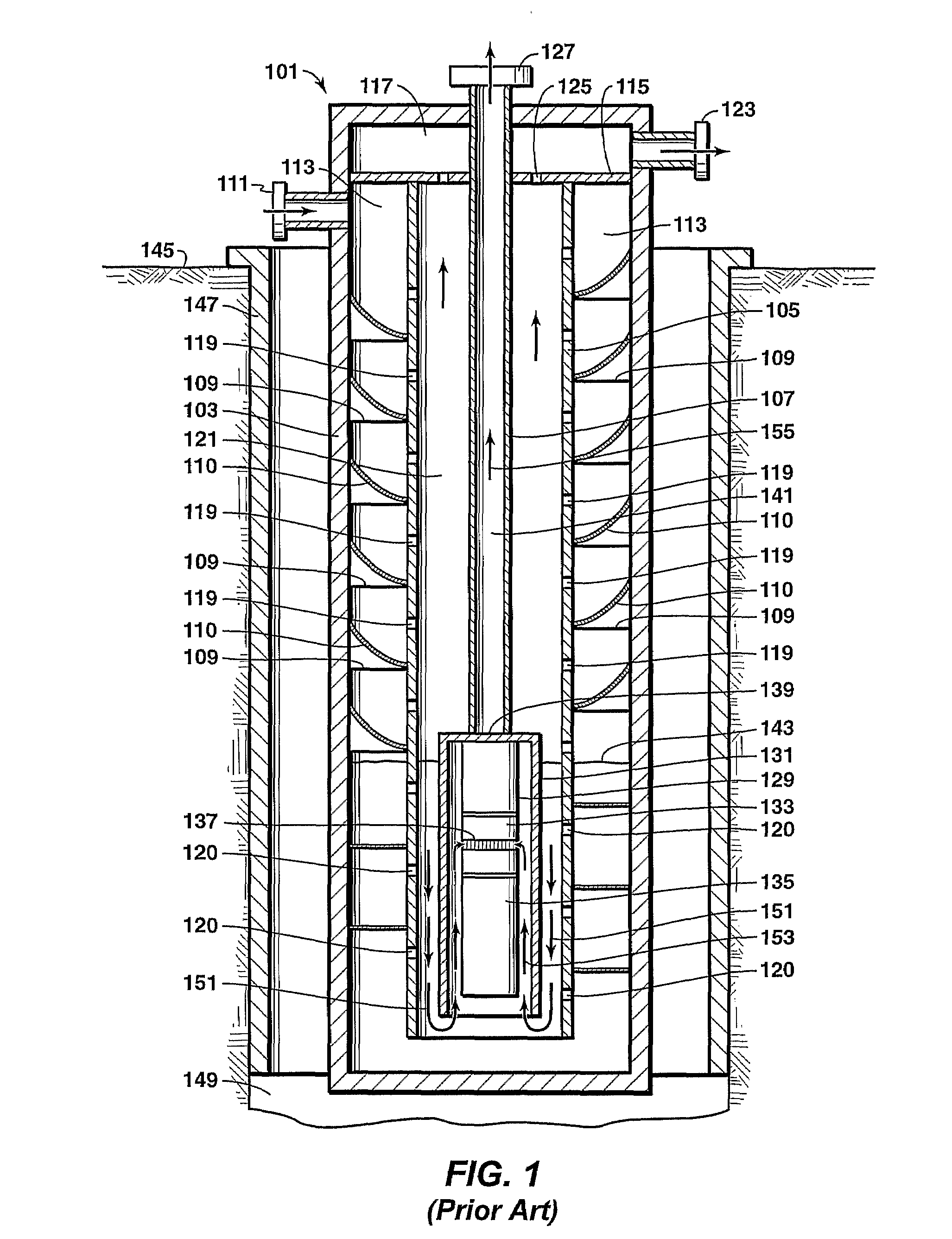
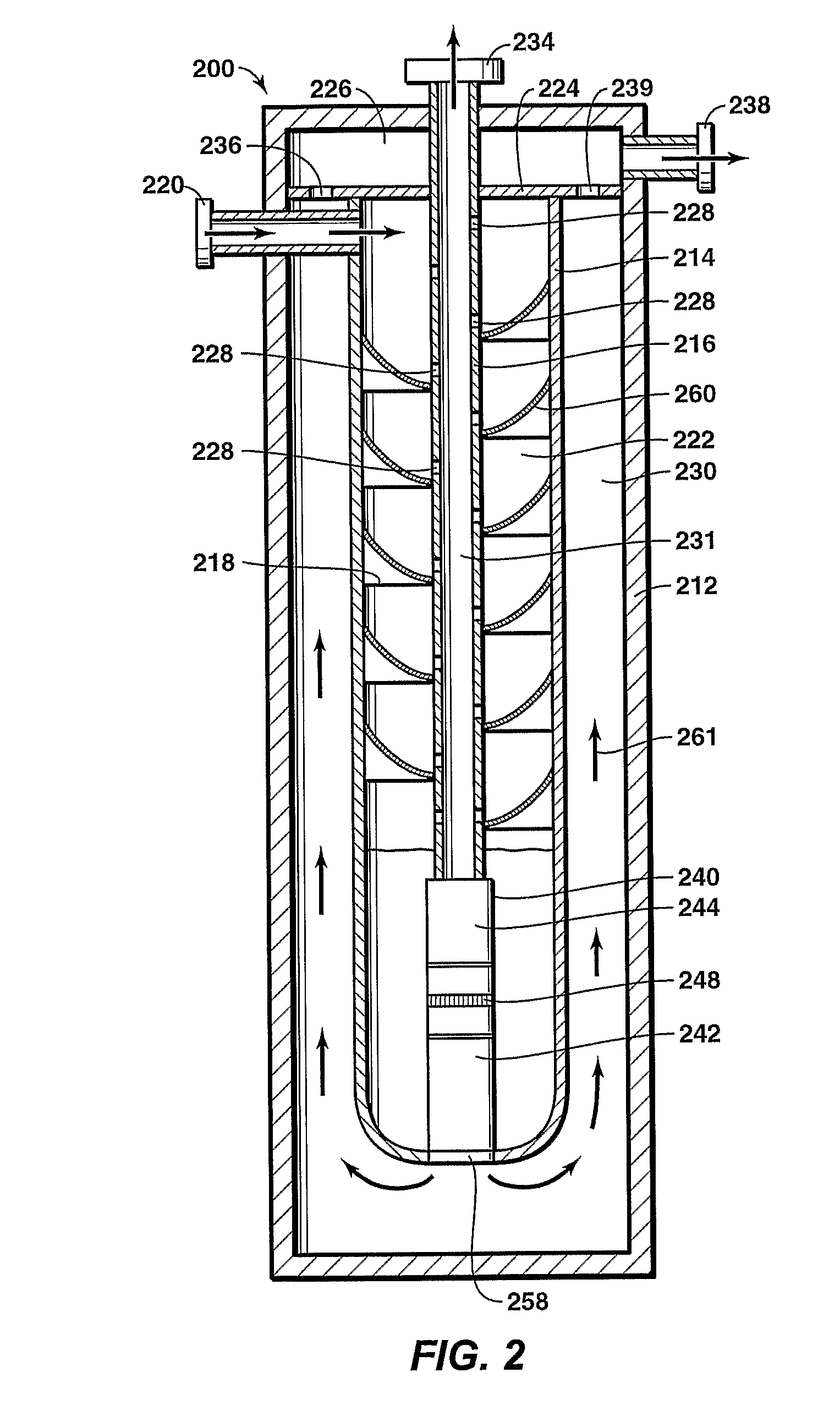
ESPs generally have difficulty (and are not particularly effective) in pumping fluids with significant volumes of
free gas as the centrifugal impellers of an ESP are typically designed for pumping fluids rather than compressing gas.
During operation, an ESP's
electric motor can produce significant amounts of heat.
In some wellbores with ESP installations, as well as in wellbores using a VASPS unit, installed pump shrouds may create numerous problems and limitations to the operations of the ESP.
An improperly mounted or damaged pump shroud can create multiple problems, such as misdirected fluid flow, which can lead to
electric motor overheating, which can in turn lead to excessive scale build-up between the
electric motor and the pump shroud, which can further lead to reduced fluid production due to scale build-up; poor
gas separation due to pump shroud leakage; overheating of the electric pump causing shortened ESP run-times between repairs; and excessive pump shroud vibrations.

