When the application of interest involves distances on the order of the
wavelength of the carrier wave, the situation is more complex and cannot be thought of as simply near-field or simply far-field.
In this case, a poor choice of reader antenna type, or the poor design of a proper type, can result in poor performance of the overall RFID
system and application failure.
Thus, in situations where UHF tags are used in RFID item tracking on shelves and other storage fixtures, the design of the reader antenna becomes critical.
The detection range of passive RFID systems is typically limited by
signal strength over short ranges, for example, frequently less than a few feet for passive UHF RFID systems.
However, portable UHF reader units suffer from several disadvantages.
The first involves the cost of human labor associated with the scanning activity.
In addition, portable units often lead to
ambiguity regarding the precise location of the tags read.
For instance, the reader location may be noted by the user, but the location of the tag during a read event may not be known sufficiently well for a given application.
Portable RFID readers can also be more easily lost or stolen than is the case for fixed reader and antenna systems.
However, such an antenna may be unwieldy, aesthetically displeasing, and the radiated power may surpass allowable legal or regulatory limits.
Furthermore, these reader antennas are often located in stores or other locations were space is at a premium and it is expensive and inconvenient to use such large reader antennas.
In addition, it should be noted that when a single large antenna is used to survey a large area (e.g., a set of retail shelves, or an entire cabinet, or entire counter, or the like), it is not possible to resolve the location of a tagged item to a particular spot on or small sub-section of the shelf fixture.
In this situation the use of a single large reader antenna is not desirable because it is not generally possible to locate the item with the desired spatial resolution.
However, the introduction of
moving parts into a commercial shelf
system may prove impractical because of higher
system cost, greater installation complexity, and higher maintenance costs, and inconvenience of system
downtime, as is often observed with machines which incorporate
moving parts.
However, as
active devices they are usually big and expensive if compared with passive antennas.
First, the antennas themselves are small, and thus require relatively little power to survey the space surrounding each antenna.
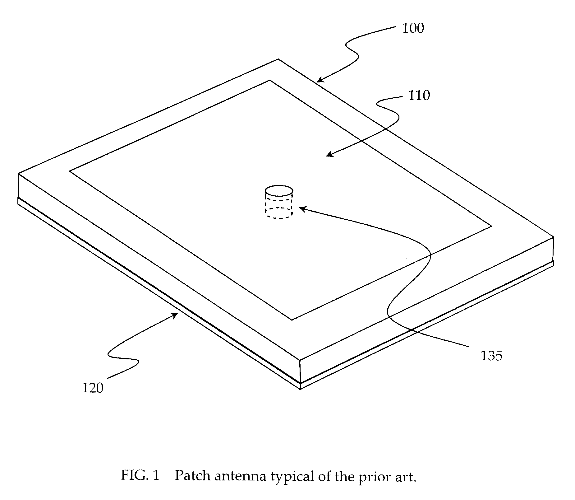
A multi-layer
antenna design can lead to excessive fabrication cost and excessive antenna thickness (complicating the
retrofitting of existing infrastructure during antenna installation, and making it more difficult to hide the antennas from view).
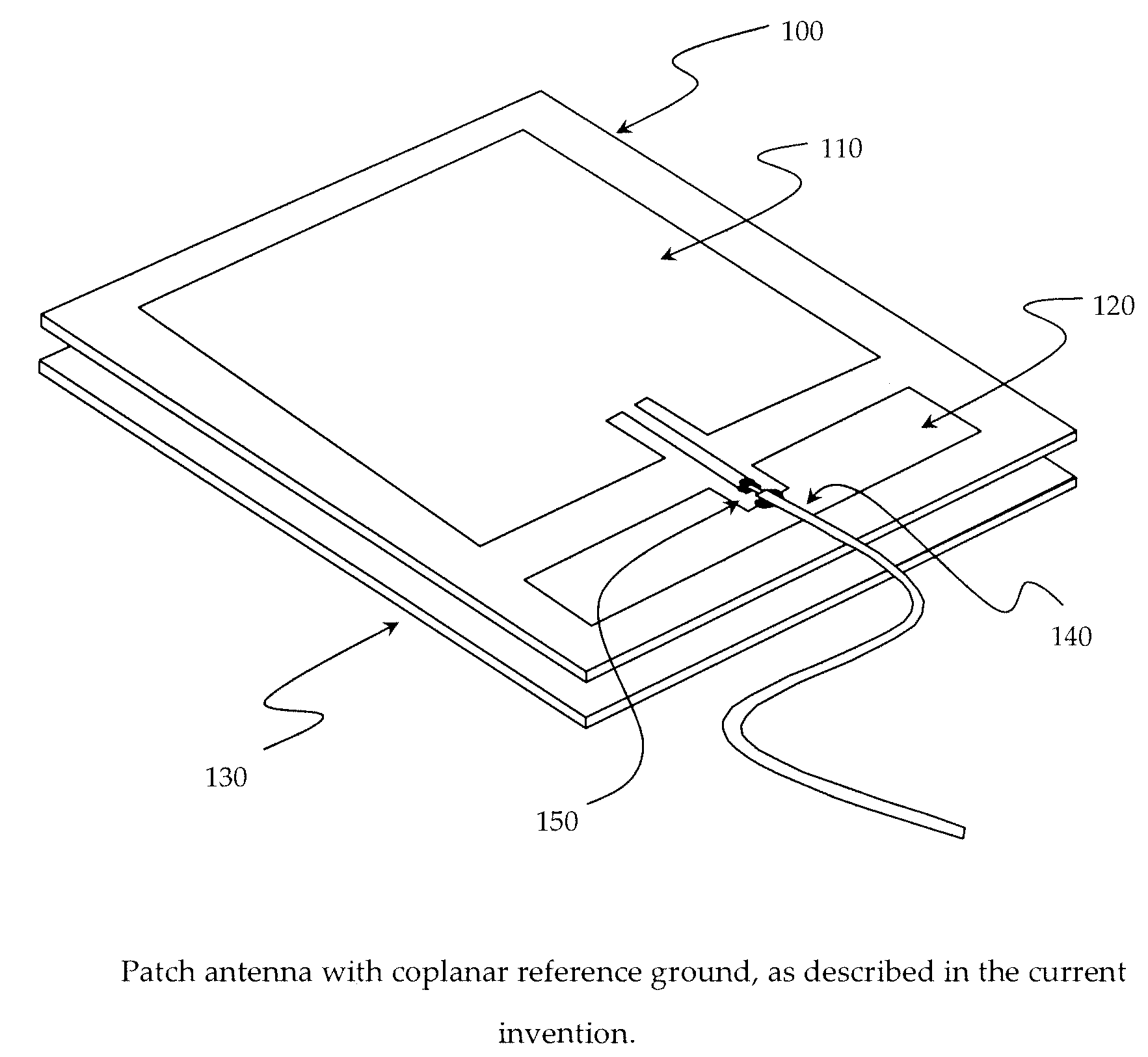
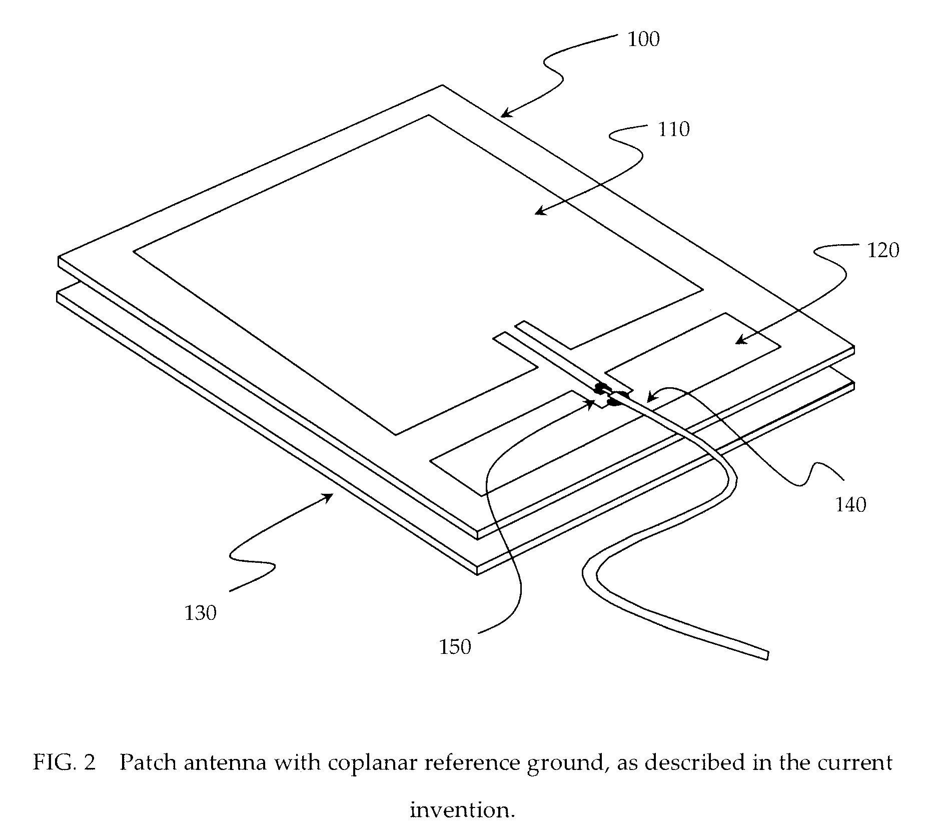
Multi-layer antenna designs also tend to complicate the form of the attachment of the connecting wires (for example, co-axial cable between the antenna and reader) since the connections of the
signal carrier and reference ground occur on different
layers, and this increases the cost of the antenna for the reasons described above.
If the bandwidth of the antenna is too narrow, the tuning of the antenna in a given application becomes very difficult, and uncontrollable changes in the environment during normal operation (such as the unanticipated and random introduction of
metal objects, human hands, or other materials into the area being monitored by the antenna) can cause a shift in
resonance frequency which, combined with the overly
narrow bandwidth, causes failure in RFID tag detection and reading.
If the
dielectric thickness or gap between the reference ground and
radiating element is too small, the radiating efficiency will be too low, and too much of the power to the antenna is wasted as heat flowing into the dielectric and surroundings.
As noted above, the relatively short
wavelength (approximately 12 inches) of UHF emissions can present challenges to the designers of UHF smart shelving who want to be able to effectively and consistently read tags at any location on the shelf.

