Systems and methods for determining vessel compliance

a technology of compliance and system, applied in the field of medical diagnostics and treatment equipment, can solve the problems of requiring ultrasound machines, requiring additional time for stent procedures, and causing angina pectoris,

Active Publication Date: 2009-08-27
3DT HLDG
View PDF36 Cites 52 Cited by
  • Summary
  • Abstract
  • Description
  • Claims
  • Application Information

AI Technical Summary

Problems solved by technology

It is likely to produce angina pectoris, heart attack or both.
However, using intravascular ultrasound as mentioned above requires a first step of advancement of an ultrasound catheter and then withdrawal of the ultrasound catheter before coronary angioplasty thereby adding additional time to the stent procedure.
Furthermore, it requires an ultrasound machine.
This adds significant cost and time and more risk to the procedure.
Although it appears that progression of AS can be more rapid in patients with degenerative calcific disease than in those with congenital or rheumatic disease, it is not possible to predict the rate of progression in an individual patient.
Problems with Current Aortic Valve Area Measurements
Such patients can be difficult to distinguish from those with low cardiac output and only mild to moderate AS.
Although valve resistance is less sensitive to flow than valve area, resistance calculations have not been proved to be substantially better than valve area calculations.
There are many other limitations in estimating aortic valve area in patients with aortic stenosis using echocardiography and cardiac catheterization.
Accurate measurement of the aortic valve area in patients with aortic stenosis can be difficult in the setting of low cardiac output or concomitant aortic or mitral regurgitations.
Furthermore, because of the dependence of aortic valve area calculation on cardiac output, any under or overestimation of cardiac output will cause inaccurate measurement of valve area.
Falsely measured aortic valve area could cause inappropriate aortic valve surgery in patients who do not need it.

Method used


Image

  • Systems and methods for determining vessel compliance
  • Systems and methods for determining vessel compliance
  • Systems and methods for determining vessel compliance

Examples


Embodiment Construction

[0057]The disclosure of the present application provides devices, systems, and methods to obtain accurate measures of the luminal cross-sectional area of organ stenosis within acceptable limits to enable accurate and scientific stent sizing and placement in order to improve clinical outcomes by avoiding under or over deployment and under or over sizing of a stent which can cause acute closure or in-stent re-stenosis. For the purposes of promoting an understanding of the principles of the present disclosure, reference will now be made to the embodiments illustrated in the drawings, and specific language will be used to describe the same. It will nevertheless be understood that no limitation of the scope of the present disclosure is thereby intended.

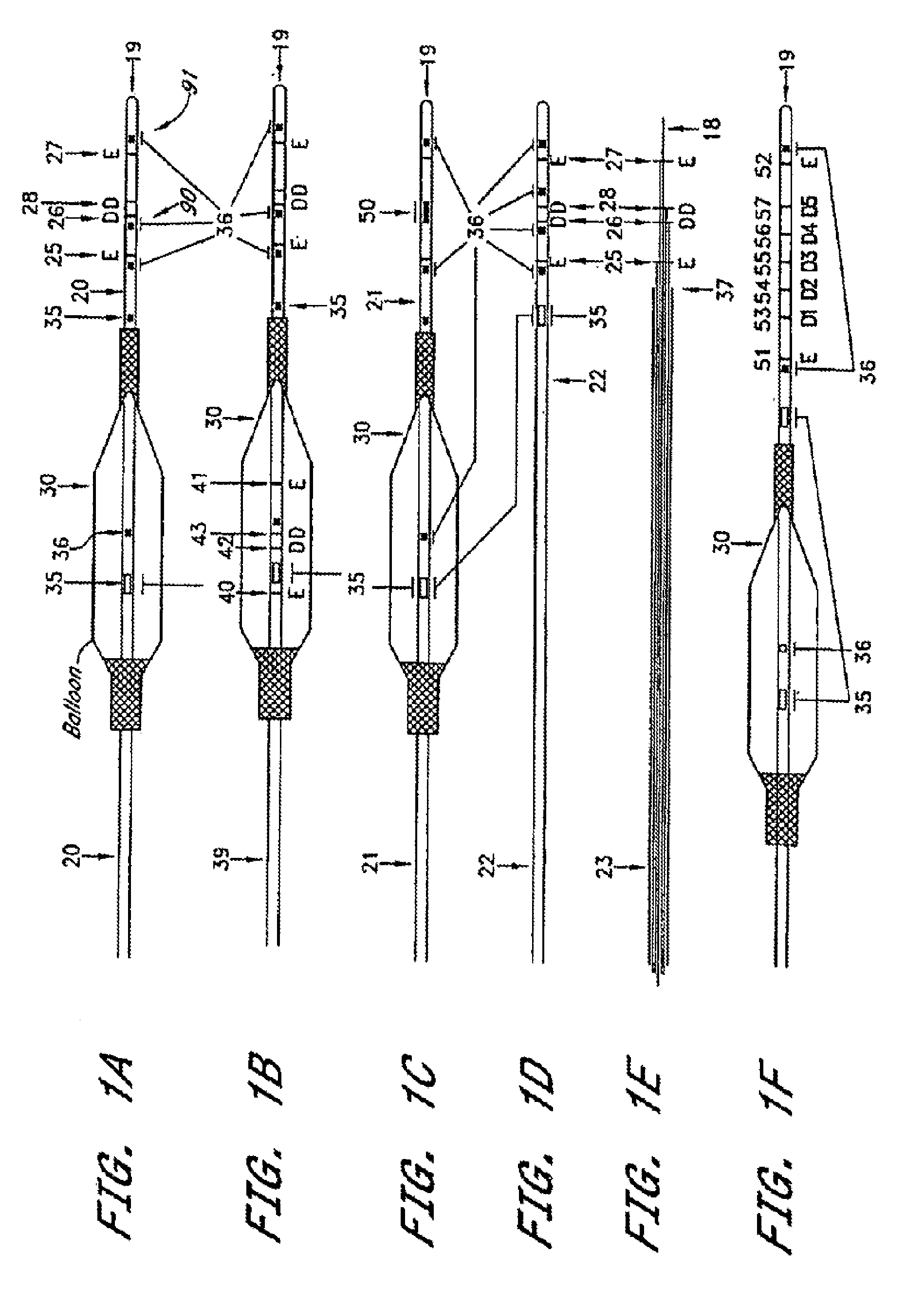
[0058]In one embodiment, an angioplasty or stent balloon includes impedance electrodes supported by the catheter in front of the balloon. These electrodes enable the immediate measurement of the cross-sectional area of the vessel during th...


PUM


Abstract

The disclosure of the present application provides for systems and methods for determining a phasic change in a vessel and vessel compliance. In at least one exemplary method for determining a phasic change in a vessel, the method comprises the steps of introducing a device into a site within a vessel, operating the device in connection with two or more fluid injections in the vessel to obtain two or more conductance values, calculating a parallel conductance value and a total conductance value, and calculating a phasic change in at least one vessel parameter based in part upon the calculated parallel conductance value and the calculated total conductance value. In an exemplary method for determining vessel compliance, the method comprises, in part, the steps of calculating a first vessel parameter and a second vessel parameter based on at least two conductance values, calculating a change in vessel parameter based upon the first and second vessel parameters, and calculating vessel compliance based upon the relationship between the change in vessel parameter and a change in pressure during a cardiac cycle.

Description

PRIORITY[0001]This U.S. patent application is a continuation application of, and claims priority to, U.S. patent application Ser. No. 12 / 426,033, filed Apr. 17, 2009, which is a continuation-in-part application of, and claims priority to, U.S. patent application Ser. No. 12 / 098,242, filed Apr. 4, 2008, which is a continuation-in-part application of, and claims priority to, U.S. patent application Ser. No. 11 / 891,981, filed Aug. 14, 2007, which is a divisional application of, and claims priority to, U.S. patent application Ser. No. 10 / 782,149, filed Feb. 19, 2004, which issued as U.S. Pat. No. 7,454,244 on Nov. 18, 2008, which claims priority to U.S. Provisional Patent Application Ser. No. 60 / 449,266, filed Feb. 21, 2003, to U.S. Provisional Patent Application Ser. No. 60 / 493,145, filed Aug. 7, 2003, and to U.S. Provisional Patent Application Ser. No. 60 / 502,139, filed Sep. 11, 2003. The contents of each of these applications are hereby incorporated by reference in their entirety int...

Claims


Application Information

Patent Timeline
Patent Type & Authority Applications(United States)
IPC IPC(8): A61B5/02
CPCA61B5/053A61B5/0538A61B2017/22051A61B2017/00026A61B5/1076
Inventor KASSAB, GHASSAN S.
Owner 3DT HLDG
Why Eureka
Try Eureka