Method for fabricating lateral-moving micromachined thermal bimorph

a micro-machined thermal bimorph and lateral movement technology, applied in the field of thermal bimorph, can solve the problems of low power method of determination, actuators do not use simple bimorph devices, and trigger sensors for such devices may require complex processing

Active Publication Date: 2009-09-03
MORGAN RES CORP
View PDF7 Cites 14 Cited by
  • Summary
  • Abstract
  • Description
  • Claims
  • Application Information

AI Technical Summary

Problems solved by technology

Current battery-powered embedded sensor systems often require a low power method of determining when a certain level of temperature has been reached.
However, the temperature trigger sensor for such a device may require complex processing to make contacts and other structures out-of-plane of the microchip.
This actuator, however, does not use a simple bimorph device but employs independently-controllable heaters that require the application of external power to operate.
In sum, none of the prior art patents discloses a micromachined thermal bimorph that displaces in a lateral direction in response to ambient temperature changes.

Method used


Image

  • Method for fabricating lateral-moving micromachined thermal bimorph
  • Method for fabricating lateral-moving micromachined thermal bimorph
  • Method for fabricating lateral-moving micromachined thermal bimorph

Examples


Embodiment Construction

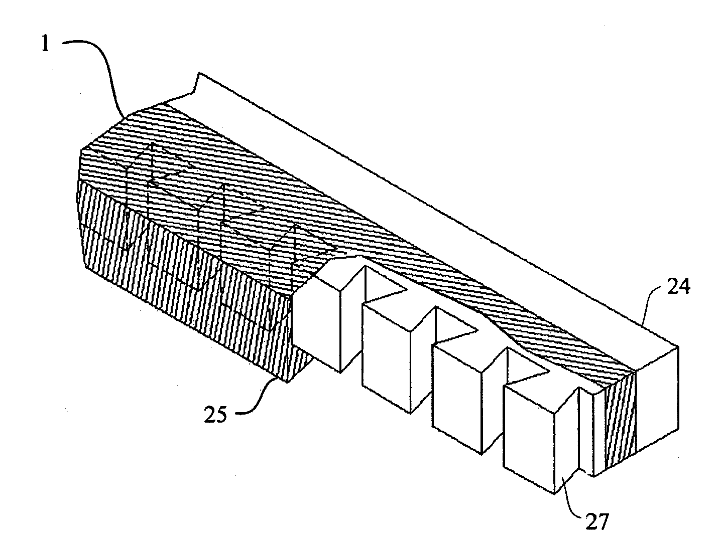
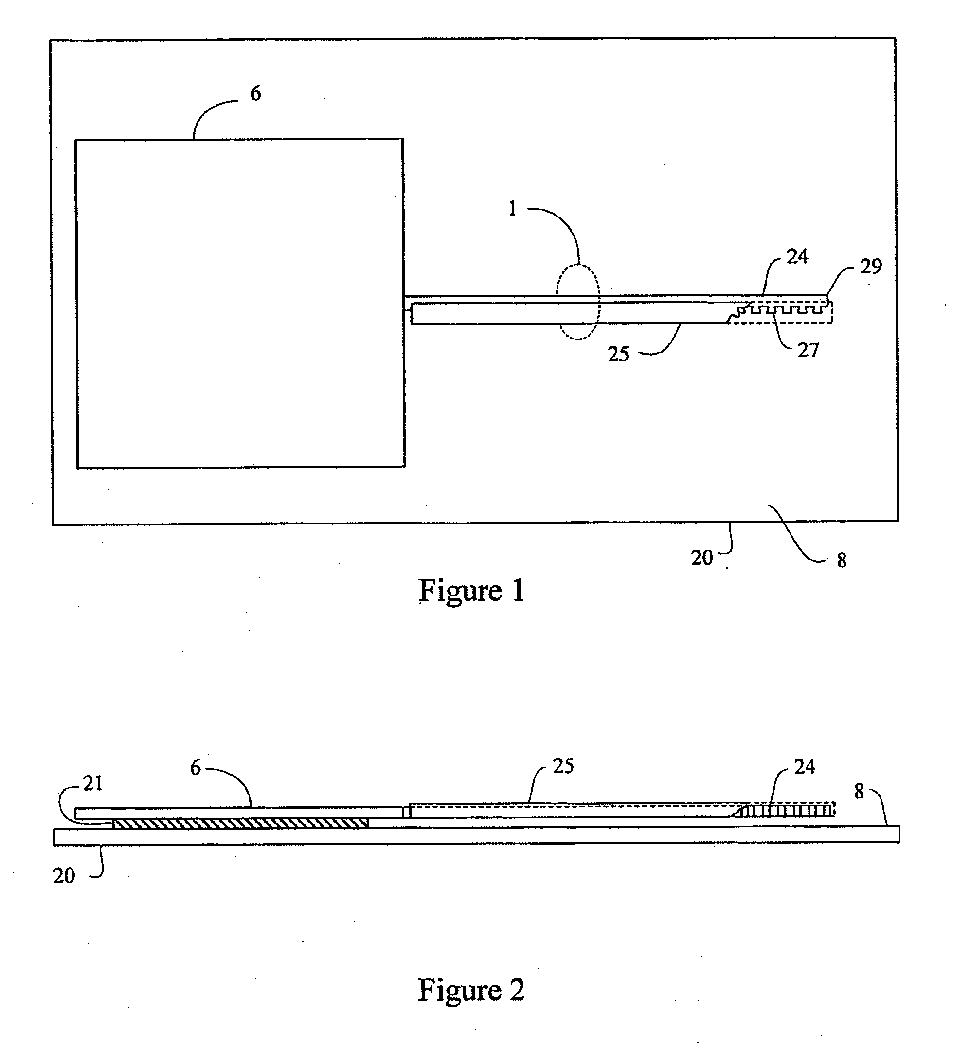
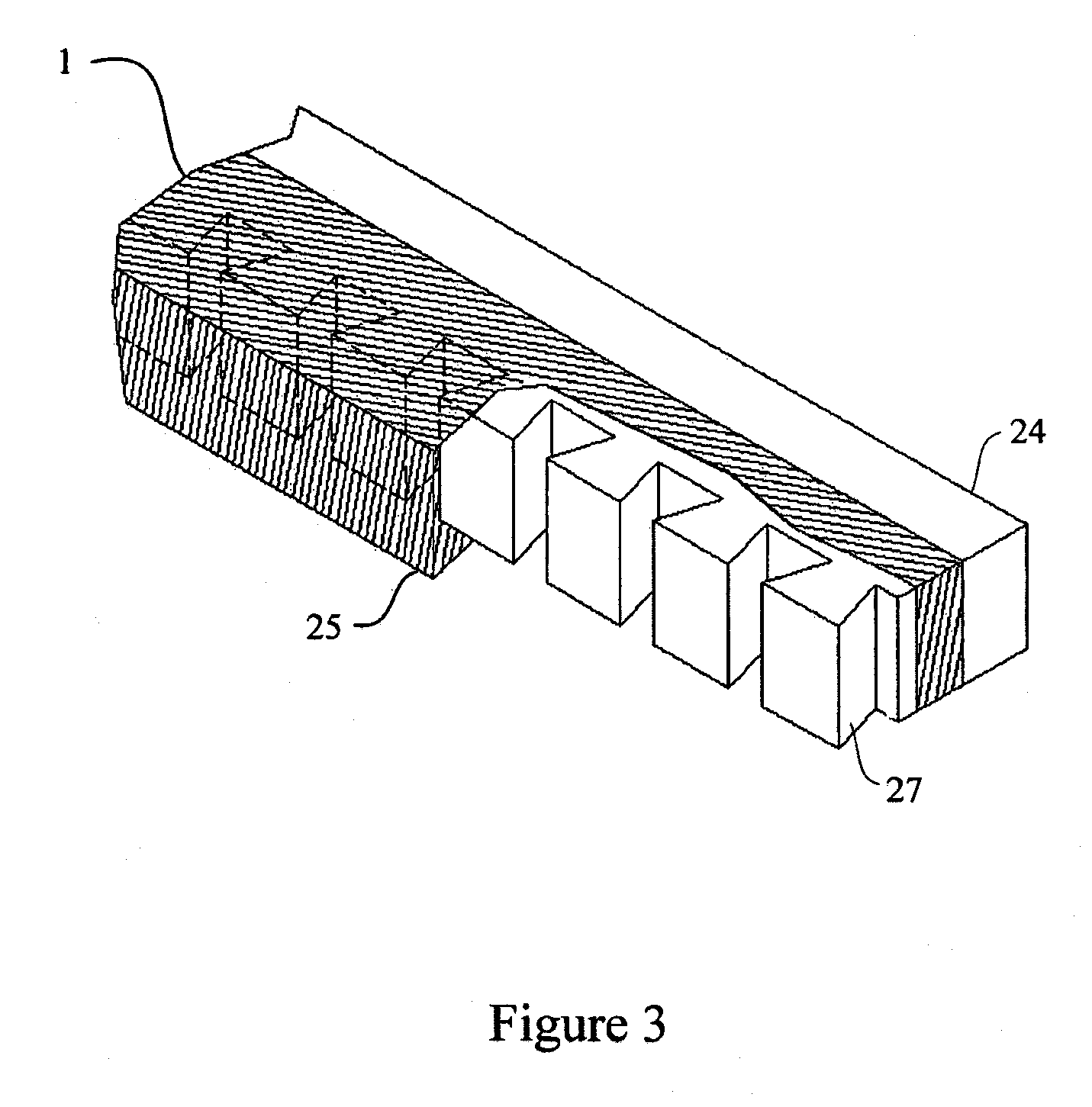
[0036]One embodiment of the invention is fabricated in a thick device layer of silicon or other conductor material on a silicon-on-insulator (“SOI”) wafer consisting of the device layer, a buried oxide layer, and a handle wafer. FIG. 1 and FIG. 2 illustrate a top and side view of this embodiment of the invention. In this embodiment, the thermal bimorph 1 consists of a micromachined cantilever beam 24 fabricated from the device layer and a sidewall coating 25 of a second, different material with a coefficient of thermal expansion mismatch to the conductor material. Upon application of a temperature load, the thermal bimorph 1 will bend so that its free end 29 moves in a lateral direction (i.e., in a direction substantially perpendicular to the length of the thermal bimorph 1 and substantially parallel to the etched surface 8 of the handle wafer 20). The thermal bimorph 1 is anchored to the handle wafer 20 via anchor 6. The sidewall coating 25 is shown in FIG. 1 and FIG. 2 as partiall...


PUM


Abstract

A method of making a Lateral-Moving Micromachined Thermal Bimorph which provides the capability of achieving in-plane thermally-induced motion on a microchip, as opposed to the much more common out-of-plane, or vertical, motion seen in many devices. The present invention employs a novel fabrication process to allow the fabrication of a lateral bimorph in a fundamentally planar set of processes. In addition, the invention incorporates special design features that allow the bimorph to maintain material interfaces.

Description

REFERENCE TO RELATED APPLICATIONS[0001]This application is a divisional of U.S. application Ser. No. 11 / 149,882, entitled, “Lateral-Moving Micromachined Thermal Bimorph and Method for Fabricating the Same” filed on Jun. 10, 2005; the disclosure of which is fully incorporated herein by reference, and claims priority to Provisional U.S. Patent Application Ser. No. 60 / 619,407 filed on Oct. 15, 2004, which is likewise fully incorporated herein by reference.GOVERNMENT LICENSE RIGHTS[0002]This invention was made with Government support under contract MDA972-03-C-0010, awarded by the Defense Advanced Research Projects Agency (“DARPA”). The Government has certain rights in the invention.BACKGROUND[0003]1. Field of the Invention[0004]The present invention relates generally to a thermal bimorph. More particularly, the present invention relates to a micromachined thermal bimorph that displaces laterally.[0005]2. Background of the Invention[0006]Current battery-powered embedded sensor systems o...

Claims


Application Information

Patent Timeline
Patent Type & Authority Applications(United States)
IPC IPC(8): H01H37/52
CPCB81B3/0078B81B2201/032B81B2203/056H01H2300/032H01H2001/0047H01H2037/008H01H37/52
Inventor ELLIOTT, ROBERT FAYEREINER, PHILIP JOHN
Owner MORGAN RES CORP
Why Eureka
Try Eureka