Umbrella system with support for internal storage of cover and external sliding ribs and stretchers

a technology of internal storage and umbrella, which is applied in the direction of umbrellas, traveling accessories, apparel, etc., can solve the problems of cumbersome sequence of manual operations required, fragile structural elements of many handheld umbrellas remaining vulnerable to wind damage, and innate disadvantages, so as to reduce potential electrical danger, and reduce the risk of damag

Inactive Publication Date: 2009-09-10
BEYER ANDREA ELGIN +1
View PDF35 Cites 19 Cited by
  • Summary
  • Abstract
  • Description
  • Claims
  • Application Information

AI Technical Summary

Benefits of technology

[0050](a) The invention provides enclosed storage space for an umbrella's retracted cover, thereby substantially preventing wet covers from transferring liquid water to exterior surfaces. The invention provides means to collect unwanted interior moisture in absorbant material and subsequently allowing passage of this moisture, by the process of evaporation, through orifices to the outside air.
[0051](b) Internal storage of said cover also has the advantage of mitigating potential damage to the cover while said cover is not in active service.
[0054](e) Allowance for umbrella construction with materials having low coefficients of electric conductivity to minimize potential electrical dangers.

Problems solved by technology

Certain umbrella concerns remain issues because devices, including many of those referenced above apparently have innate disadvantages.
Examination of several teachings addressing concerns about the tendency of umbrella coverings to drip while furled reveal pervasive problems.
While this invention offers protection to its stowed cover, the sequence of manual operations required appears to be cumbersome for convenient transitions between cane and umbrella modes.
Today, over a century later, fragile structural elements of many handheld umbrellas remain vulnerable to wind damage.
Furthermore, in today's economy, the labor intensive process of repairing umbrella mechanisms is not cost effective.
Structures taught are complex and fragile.
Components are in the tradition of umbrella deployment structures vulnerable to irreversible damage from excessive wind forces.
It further exemplifies ubiquitous, fragile construction of some contemporary handheld umbrella deployment mechanisms.
Such construction increases dangers from ambient high voltage electricity such as that associated with lightning storms.
However the invention still contains fragile linkage joints susceptible to high wind events that might exceed elastic limits of plastic elements, possibly resulting in permanent damage to the umbrella.
As is inherent in such arrangements, gusts of winds tend to invert frames consisting only of ribs that lack the reinforcement provided by stretchers.
As in the previous example, a significant difficulty with this system is relatively low rigidity provided to its deployed cover.
In practice, it remains hard to imagine an elongated member capable of bending from an essentially vertical orientation during cover storage, then curling to a radial configuration, while also being capable, without additional support, of resisting compromising effects of wind and other potentially deforming forces.
This configuration appears to be unable to enforce ample congruency between cover and extended ribs.
Furthermore, by their inherent rigidity, extending ribs of this disclosure appear rather vulnerable to excessive winds that could exceed structural limitations, thereby resulting in permanent deformation.
Such unfortunate results are commonly seen in damaged umbrellas.
It appears to be a rather cumbersome solution.
Another issue of umbrella construction is a tendency of wet covers on handheld models to drip after being furled.
Clothing, contents of brief cases, purses, flooring, and furniture all may be compromised by coming into contact with wet retracted umbrellas.
Such cylinders appear to present a somewhat unwieldy package when retracted on an umbrella stick.

Method used


Image

  • Umbrella system with support for internal storage of cover and external sliding ribs and stretchers
  • Umbrella system with support for internal storage of cover and external sliding ribs and stretchers
  • Umbrella system with support for internal storage of cover and external sliding ribs and stretchers

Examples


Embodiment Construction

LIST OF REFERENCE NUMERALS UTILIZED IN THE DRAWING

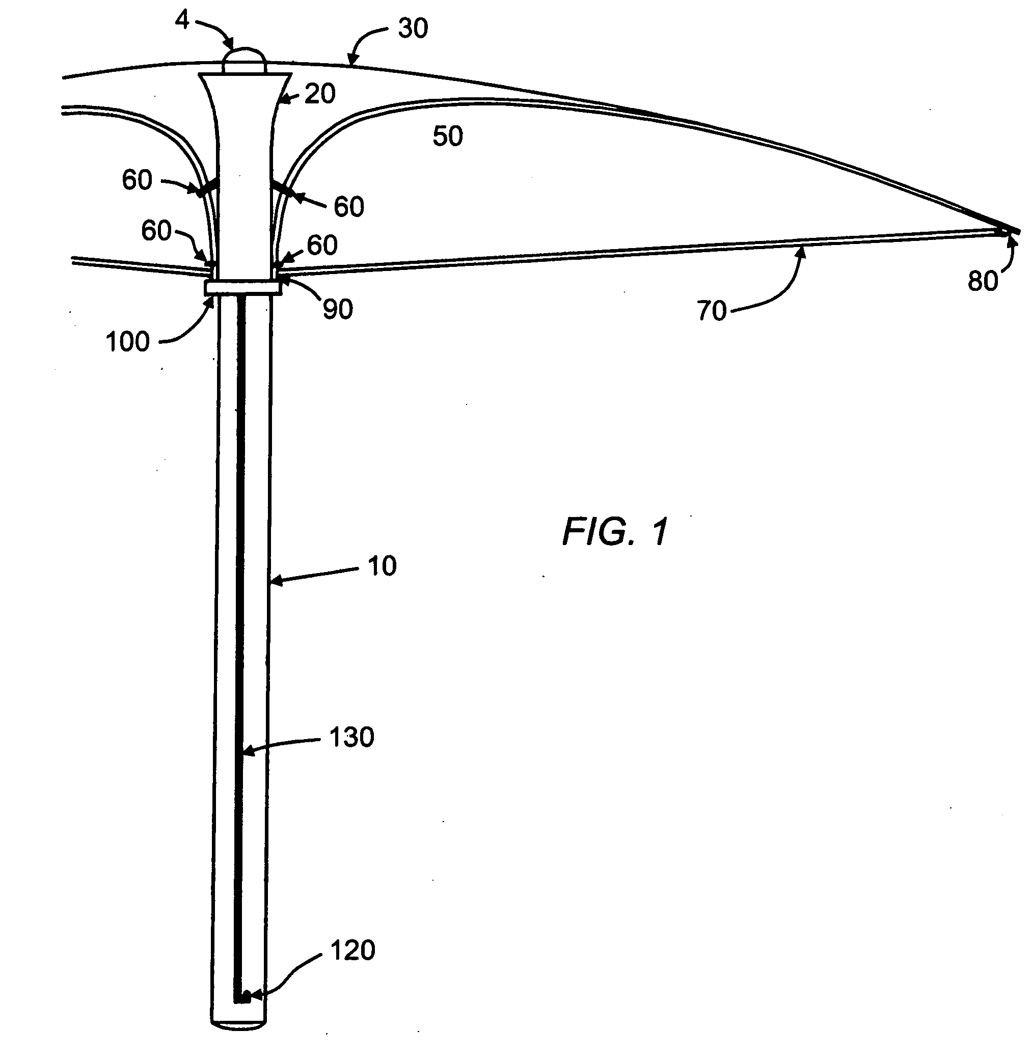
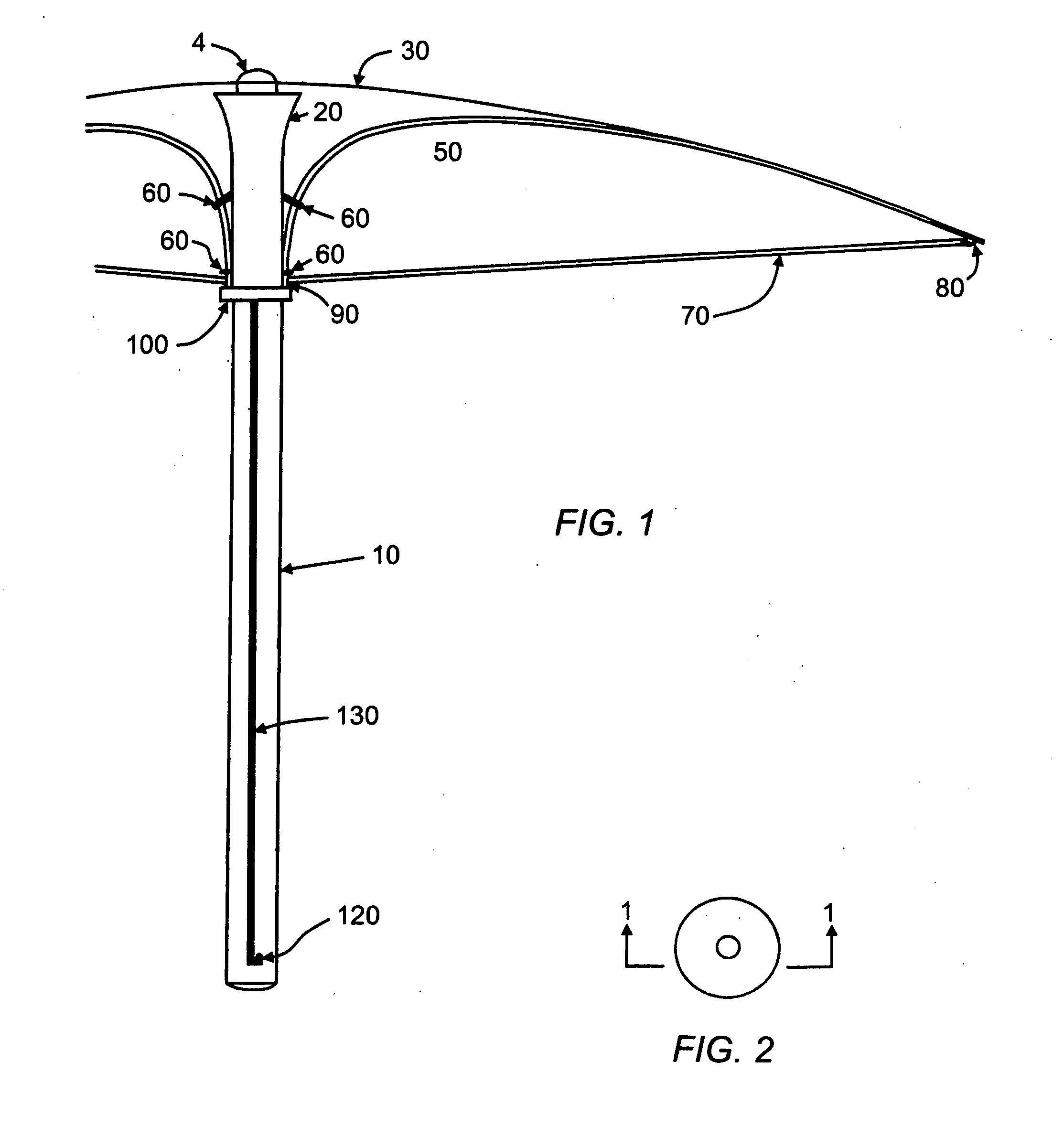
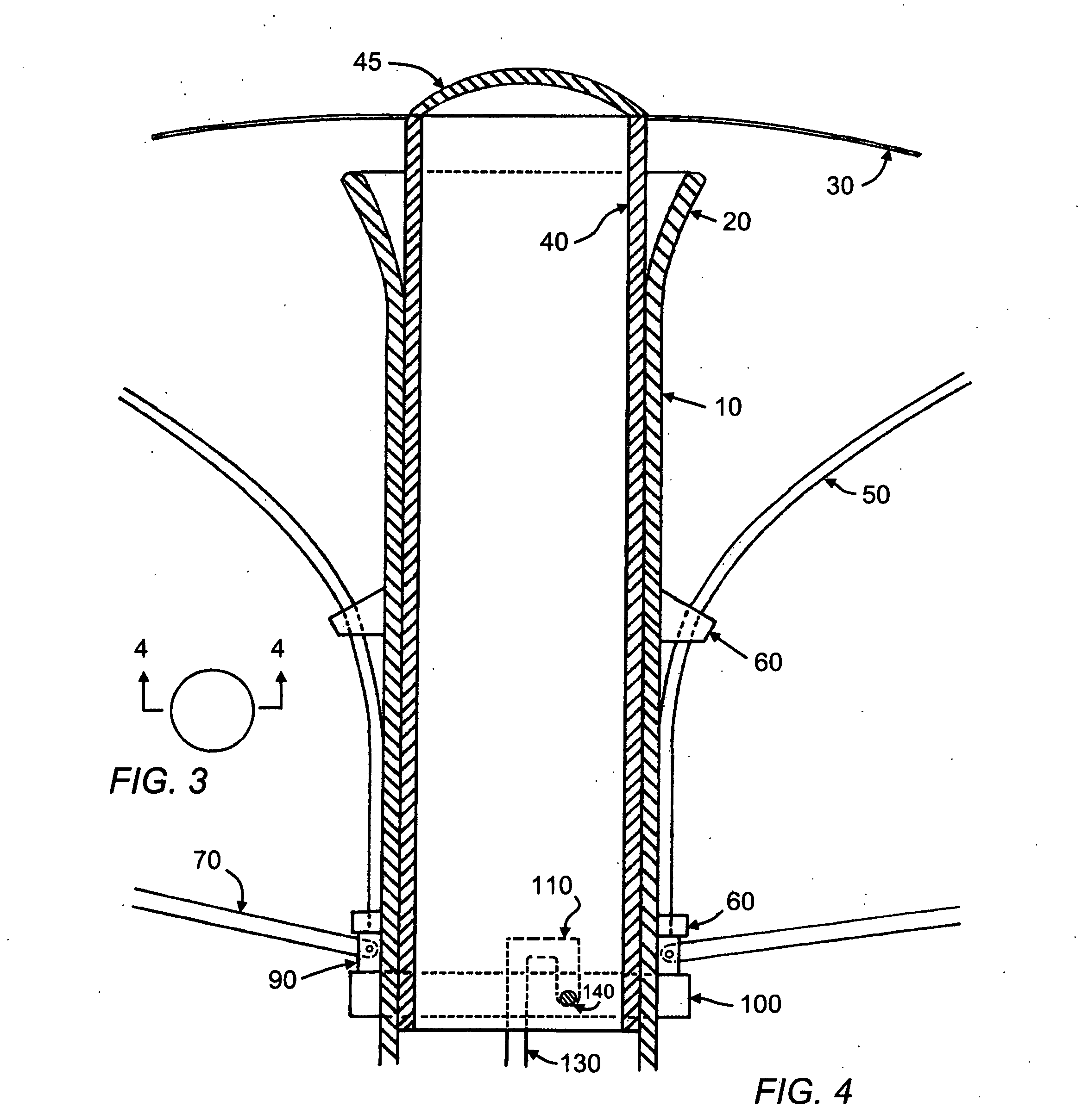
[0074]10 hollow shaft

[0075]20 upper transition element

[0076]30 cover

[0077]40 cover hub slider

[0078]45 cover-cover hub attachment devices

[0079]50 rib

[0080]60 rib collimator

[0081]70 stretcher

[0082]80 cover-rib-stretcher fastener

[0083]90 stretcher-rib slider

[0084]100 deployment slider

[0085]110 deployment slider upper fastener

[0086]120 deployment slider lower fastener

[0087]130 track slot

[0088]140 deployment slider-cover hub slider slot link

[0089]150 membrane support

[0090]160 cap

[0091]170 orifices

[0092]180 vapor permeable membrane

[0093]190 absorbant material

[0094]200 track slot gasket / internal moisture barrier

[0095]210 cover-rib tether

[0096]220 tether link

[0097]230 sleeve storage vessel

[0098]240 sleeve

[0099]250 handle cylinder

[0100]260 support elements

DETAILED DESCRIPTION OF THE INVENTION

[0101]A typical embodiment of this invention is shown on SHEET 1 / 6, FIG. 1, as an umbrella with a hollow shaft 10, providing means for containment, deplo...


PUM


Abstract

The present invention relates to an umbrella system, substantially comprising an umbrella with elements that include a hollow shaft, a cover, as well as a frame consisting of ribs and stretchers mounted on the exterior of the hollow shaft. When retracted, the cover is stowed inside the shaft. When deployed, the umbrella's cover is supported by ribs and stretchers as well as by the shaft. Ribs and stretchers slide along the hollow shaft's exterior as the invention's cover is deployed and retracted.This configuration of deployment elements is not seen in the prior art of umbrella construction. It allows use of accouterments that expand the invention's use and convenience.The umbrella may be constructed using materials having low coefficients of electrical conductivity such fiberglass, plastics, or composites, thereby reducing shock risks. The manner of the invention's construction also enhances its ability to resist damage due to excessive wind as well as unwanted transfer of moisture from its retracted cover.

Description

CROSS-REFERENCE TO RELATED APPLICATIONS[0001](Not Applicable)STATEMENT REGARDING FEDERALLY SPONSORED RESEARCH OR DEVELOPMENT[0002](Not Applicable)REFERENCE TO A SEQUENCE LISTING.[0003](Not Applicable)BACKGROUND OF THE INVENTION[0004]Many types of umbrellas are in use worldwide. Outdoor experiences are enhanced by their availability for the interdiction of adverse environmental factors. Umbrella sizes range from small handheld models to large mounted structures capable of shielding several people.[0005]Along with known benefits of umbrellas, it is generally acknowledged that some vexing issues may compromise their use. Excessive wind is a particular bane. Handheld models are often subject to irreversible damage during high wind events. It is not unusual to see many wrecked and discarded umbrellas along sidewalks-after windy storms. While the delicate linkages in many handheld umbrellas are particularly subject to wind damage, even the more substantial “garden” varieties may also suff...

Claims


Application Information

Patent Timeline
Patent Type & Authority Applications(United States)
IPC IPC(8): A45B25/00A45B25/24A45B25/02
CPCA45B19/00A45B25/18A45B23/00
Inventor BEYER, ANDREA ELGINBEYER, STEVEN LARSEN
Owner BEYER ANDREA ELGIN
Why Eureka
Try Eureka