System, device and method for on-site wastewater processing

a wastewater treatment and system technology, applied in water cleaning, membranes, separation processes, etc., can solve the problems of septic tank effluent not meeting, water quality emission, drainflelds often failing, etc., to achieve sufficient clean water, reduce pore size, and reduce the effect of pore siz

Inactive Publication Date: 2009-09-10
GAUTHIER RAY
View PDF10 Cites 10 Cited by
  • Summary
  • Abstract
  • Description
  • Claims
  • Application Information

AI Technical Summary

Benefits of technology

[0003]A modular wastewater clarification device that may be positioned external to a septic tank or, alternatively, installed internally within a septic tank chamber to produce sufficiently clean water for lawn and agricultural uses. The modular clarification device includes a filter having a smaller size than the pre-filter bridging between the primary and secondary chambers of a septic tank. In one embodiment, the modular filtration unit resides outside the two-chambered septic tank and receives pre-filtered septic tank effluent fluids stored in the secondary chamber that has accumulated pre-filtered effluent. In another embodiment, the modular wastewater clarification device resides inside the secondary chamber and filters the accumulated pre-filtered effluent. The modular filtration device, having a substantially smaller pore size range than the inter-chamber pre-filter, releases clean water having substantially lowered bacterial and waste related impurities sufficient to meet water release standards suitable for lawn, garden, and agricultural uses.

Problems solved by technology

Effluents from septic tanks may no longer meet the new water quality emission standards now in force in various municipalities and other governmental jurisdictions.
Alternatively, drainflelds often fail due to overloading.

Method used


Image

  • System, device and method for on-site wastewater processing
  • System, device and method for on-site wastewater processing
  • System, device and method for on-site wastewater processing

Examples


Embodiment Construction

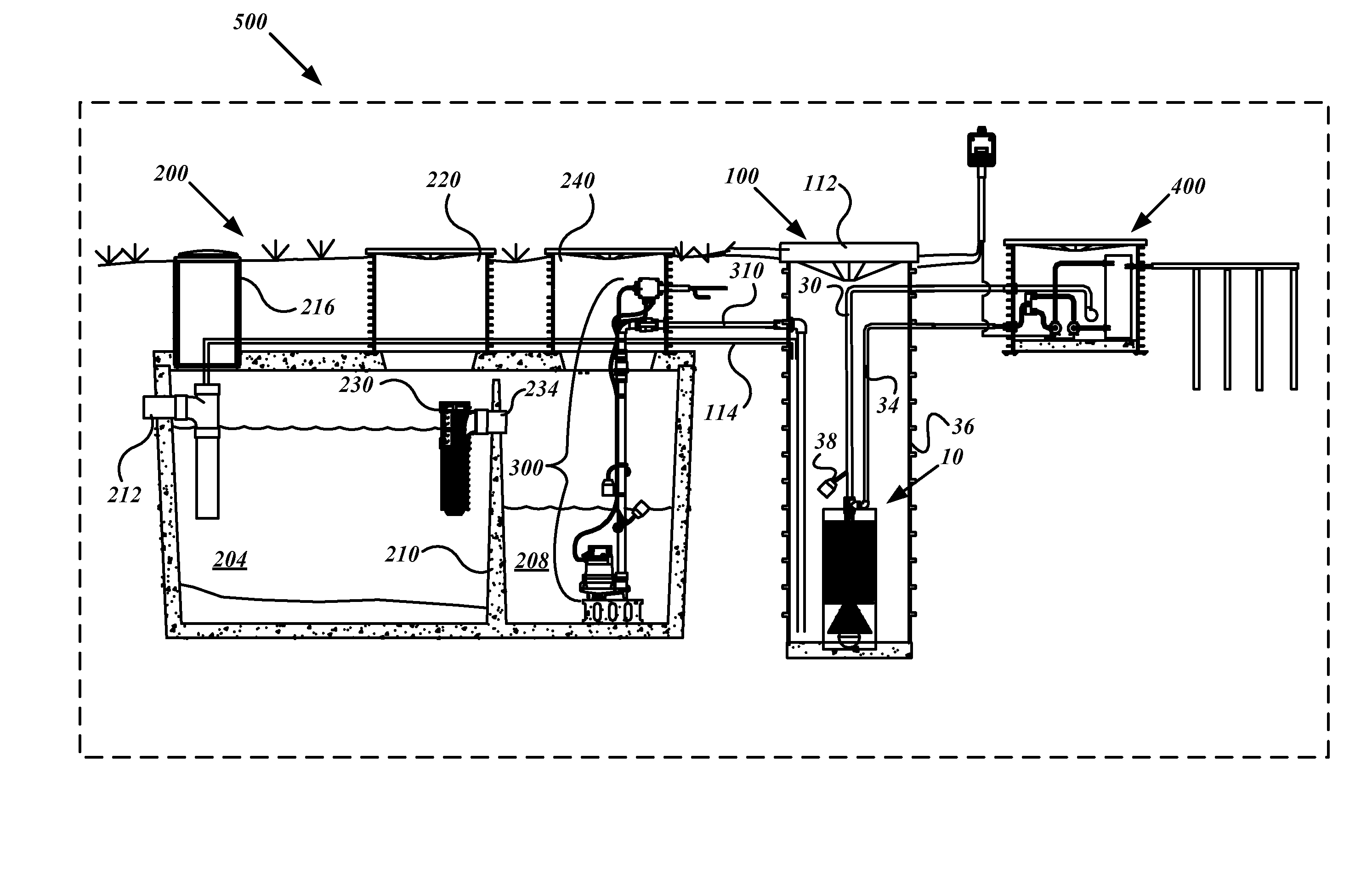
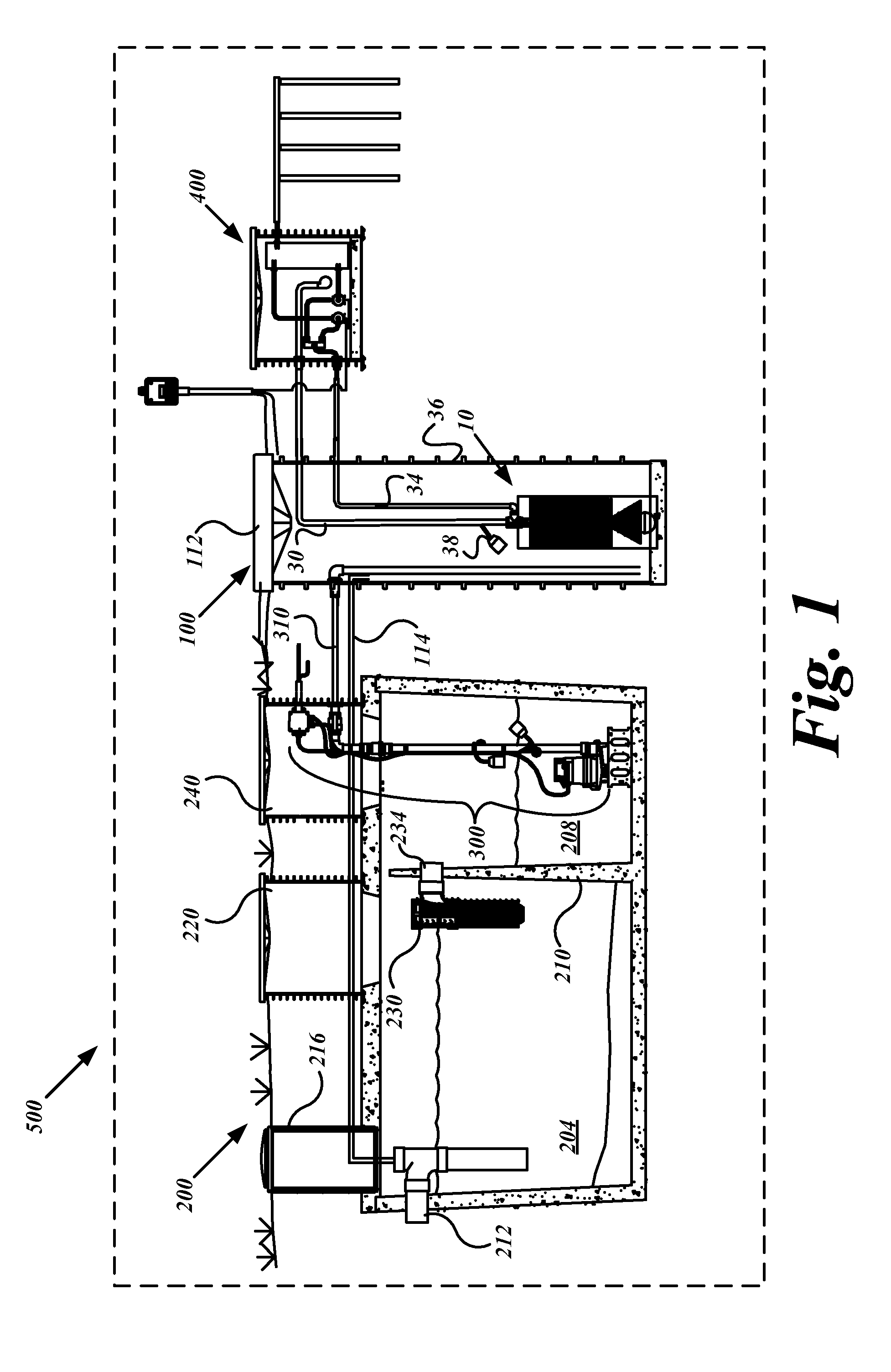
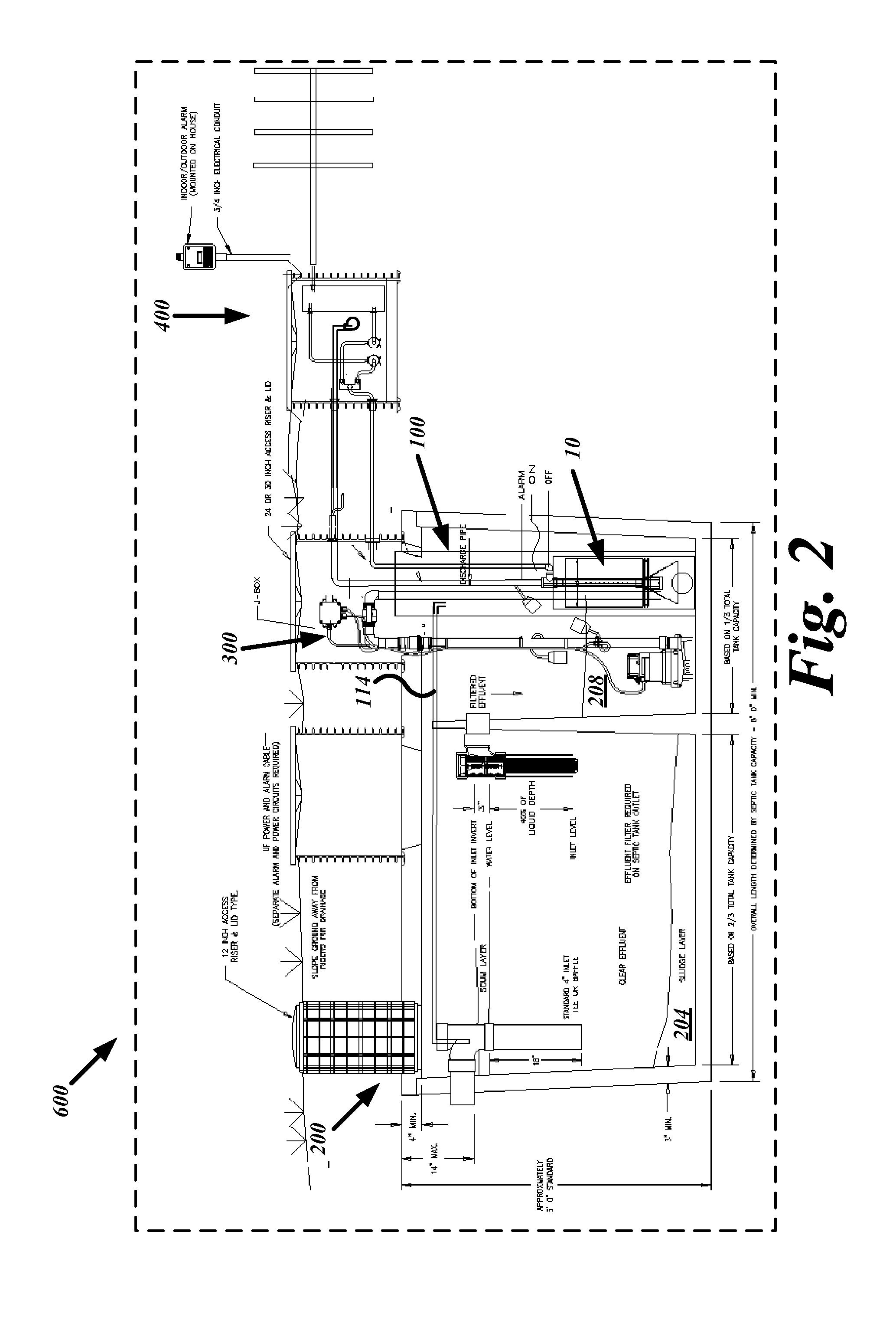
[0020]FIGS. 1-12 below illustrate particular embodiments of systems and methods for on-sight wastewater processing and water-remediation. In general, a septic tank pre-filters fluids from primary waste sewage with a filter media having a first porosity. The first porosity may include pore sizes in the approximate range of 1 / 32 to 1 / 16 inch to provide a fluid effluent that has gross to medium size particulates removed above this range. The waste fluid effluent is then clarified to clean water status through a filter media having a second porosity. The filtration media within the modular filtration device may be spiral, plate and frame, or other filtration media configurations wherein the second porosity may include a pore size in the range of 0.05 to 0.1 micron diameter. The clean water permeate or filtrate is substantially reduced in bacterial count and any sub-micron indissoluble particulates to render a water quality suitable for lawn and garden, dissemination of clean water to dr...


PUM

PropertyMeasurementUnit
diameteraaaaaaaaaa
diameteraaaaaaaaaa
diameteraaaaaaaaaa

Abstract

A modular wastewater clarification device that may be positioned external to a septic tank or, alternatively, installed internally within a septic tank chamber to produce sufficiently clean water for lawn and agricultural uses. The modular clarification device includes a filter having a smaller size than the pre-filter bridging between the primary and secondary chambers of a septic tank. In one embodiment, the modular filtration unit resides outside the two-chambered septic tank and receives pre-filtered septic tank effluent fluids stored in the secondary chamber that has accumulated pre-filtered effluent. In another embodiment, the modular wastewater clarification device resides inside the secondary chamber and filters the accumulated pre-filtered effluent. The modular filtration device, having a substantially smaller pore size range than the inter-chamber pre-filter, releases clean water having substantially lowered bacterial and waster related impurities sufficient to meet water release standards suitable for lawn, garden, and agricultural uses.

Description

FIELD OF THE INVENTION[0001]This invention relates generally to filtration devices and systems for producing clean water from sewage sources, particularly clean water from sewage stored in septic tanks.BACKGROUND OF THE INVENTION[0002]Effluents from septic tanks may no longer meet the new water quality emission standards now in force in various municipalities and other governmental jurisdictions. It is advantageous to have an economical solution to bring existing and current septic tank systems in conformity to the new water quality release standards. Alternatively, drainflelds often fail due to overloading. It is advantageous to have an economical solution for the remediation of failed systems.SUMMARY OF THE INVENTION[0003]A modular wastewater clarification device that may be positioned external to a septic tank or, alternatively, installed internally within a septic tank chamber to produce sufficiently clean water for lawn and agricultural uses. The modular clarification device in...

Claims


Application Information

Patent Timeline
Patent Type & Authority Applications(United States)
IPC IPC(8): C02F3/30
CPCB01D61/18B01D63/10B01D65/02C02F3/30B01D2321/185C02F1/444C02F3/1242B01D2315/06Y02W10/10
Inventor GAUTHIER, RAY
Owner GAUTHIER RAY
Why Eureka
Try Eureka