Diffraction grating device, laser diode, and wavelength tunable filter

a wavelength tunable filter and laser diode technology, applied in the direction of instruments, semiconductor lasers, optical elements, etc., can solve the problems of poor reproducibility of reflectivity, especially the reflectivity at the peak wavelength, and the complex structure of the grating to achieve uniform reflectivity at a plurality of peak wavelengths. , to achieve the effect of small wavelength dependen

Inactive Publication Date: 2009-09-10
SUMITOMO ELECTRIC IND LTD
View PDF6 Cites 34 Cited by
  • Summary
  • Abstract
  • Description
  • Claims
  • Application Information

AI Technical Summary

Benefits of technology

[0037]According to this wavelength tunable filter, a wavelength tunable filter having a reflectivity with small wavelength dependence can be provided by using the vernier effect caused by a combination of the ring resonator or the Fabry-Perot etalon and the diffraction grating device.
[0038]The diffraction grating device, laser diode, and wavelength tunable filter described above can be formed on, for example, a semiconductor substrate. Alternatively, these devices can be formed on an optical waveguide on a quartz substrate or a silicon (Si) substrate. In addition, these devices can be optically coupled with a semiconductor device including a waveguide having an optical gain. When the vernier effect is used, the reflection spectrum can be controlled by a change in the refractive index due to a temperature change.

Problems solved by technology

In the case where the non-uniform gratings of the wavelength tunable laser described in Non-Patent Document 1 are super-structure gratings, the structure of the gratings is so complicated to obtain uniform reflectivity at a plurality of peak wavelengths.
Furthermore, the reproducibility of reflectivity, especially the reflectivity at the peak wavelength, is poor because of an effect of a production error.

Method used


Image

  • Diffraction grating device, laser diode, and wavelength tunable filter
  • Diffraction grating device, laser diode, and wavelength tunable filter
  • Diffraction grating device, laser diode, and wavelength tunable filter

Examples


Embodiment Construction

[0057]The finding of the present invention can be easily understood by considering a detailed description below with reference to the attached drawings shown as exemplifications. Diffraction grating devices, laser diodes, and wavelength tunable filters according to embodiments of the present invention will now be described with reference to the attached drawings. The same components are assigned the same reference numerals for each possible case.

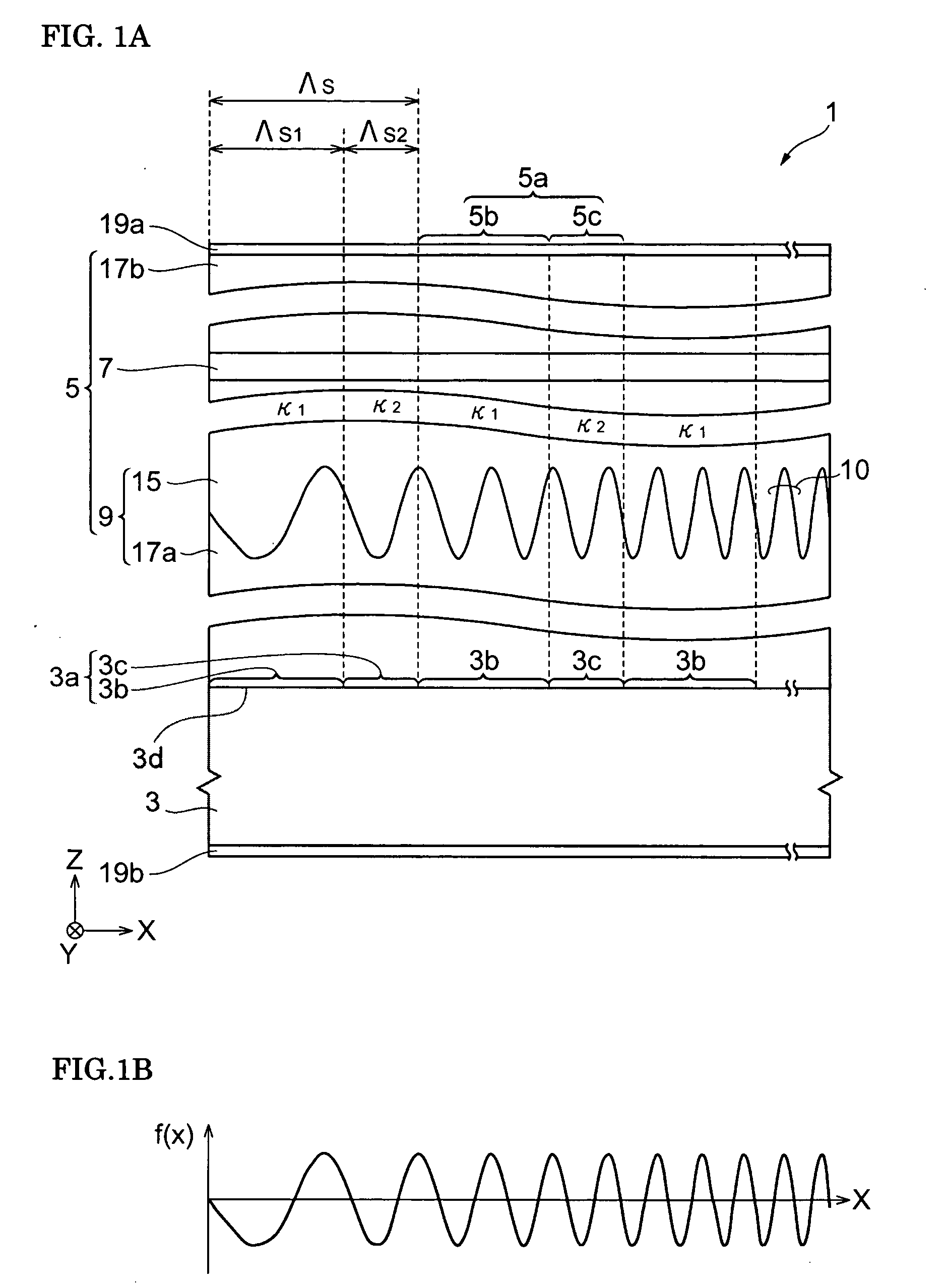
[0058]FIG. 1A is a schematic view showing the structure of a diffraction grating device according to an embodiment. Referring to FIG. 1A, a rectangular coordinate system S is shown. A diffraction grating device 1 includes a substrate 3 and a stacked structure 5 with a plurality of layers. The substrate 3 has a primary surface 3d. The primary surface 3d includes a plurality of grating areas 3a with first areas 3b and second areas 3c. The grating areas 3a with a constant period Λs are periodically arranged in a direction of a predetermined axi...


PUM

PropertyMeasurementUnit
length Λs1aaaaaaaaaa
length Λs2aaaaaaaaaa

Abstract

A diffraction grating device includes a substrate with a primary surface having a plurality of grating areas that are periodically arranged with a constant period in a predetermined axis direction, the grating area including a first area and a second area, a diffraction grating structure providing a chirped grating whose pitch monotonically changes along the predetermined axis direction, a core layer that is optically coupled with the diffraction grating structure with a coupling coefficient, a plurality of grating portions including the diffraction grating structure and the core layer, the grating portion including a first portion and second portion that are arranged on the first area and the second area, respectively, of the primary surface and a perturbing layer disposed at the first portion or the second portion. The perturbing layer changes the coupling coefficient between the diffraction grating structure and core layer. A periodical change in the coupling coefficient is formed along the core layer, and this change in the coupling coefficient affects the light propagating through the core layer in the direction of the predetermined axis.

Description

BACKGROUND OF THE INVENTION[0001]1. Field of the Invention[0002]The present invention relates to a diffraction grating device, a laser diode, and a wavelength tunable filter.[0003]2. Description of the Related Art[0004]Non-Patent Document 1 (Optical integrated device, Kohroh Kobayashi, Kyoritsu Shuppan Co., Ltd., 1999, p. 116) describes a wavelength tunable laser including a pair of non-uniform gratings. The non-uniform gratings have a plurality of peaks of reflectivity in a reflection spectrum thereof. In addition, a gain region (active layer) is provided between the pair of non-uniform gratings. In this wavelength tunable laser, the lasing wavelength is changed by injecting a current to each of the non-uniform gratings. Furthermore, by using the vernier effect, the lasing wavelength is significantly changed by injecting a small current into each of the non-uniform gratings. A sampled grating and a super-structure grating are described as the structure of the non-uniform grating.SU...

Claims


Application Information

Patent Timeline
Patent Type & Authority Applications(United States)
IPC IPC(8): H01S3/10G02B5/18H01S3/08G02F1/03H01S5/12
CPCG02F1/225G02F2203/15H01S5/028H01S5/06256H01S5/3211H01S5/1203H01S5/1206H01S5/1212H01S5/12
Inventor KATO, TAKASHI
Owner SUMITOMO ELECTRIC IND LTD
Why Eureka
Try Eureka