River and tidal power harvester

a technology of river and tidal power, applied in the field of energy, can solve the problems that wind turbines also require complex onsite construction and manpower, and achieve the effect of minimal upfront funding and low build, installation and service costs

Inactive Publication Date: 2009-09-17
CATLIN CHRISTOPHER S
View PDF36 Cites 96 Cited by
  • Summary
  • Abstract
  • Description
  • Claims
  • Application Information

AI Technical Summary

Benefits of technology

[0020]The invention's advantages over current state of the art hydrokinetic devices are numerous and include lower build, install and service costs. Minimal upfront f...

Problems solved by technology

Wind turbines also require comp...

Method used


Image

  • River and tidal power harvester
  • River and tidal power harvester
  • River and tidal power harvester

Examples


Embodiment Construction

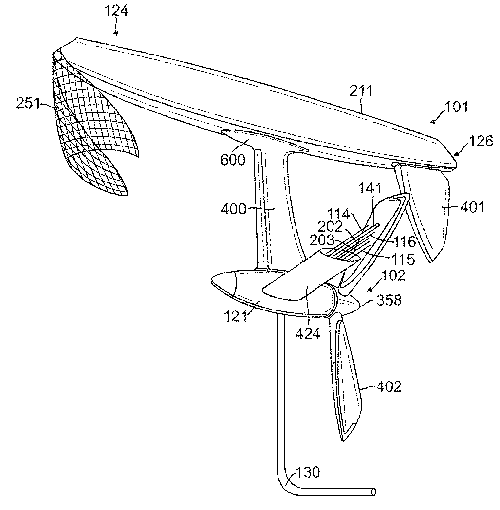
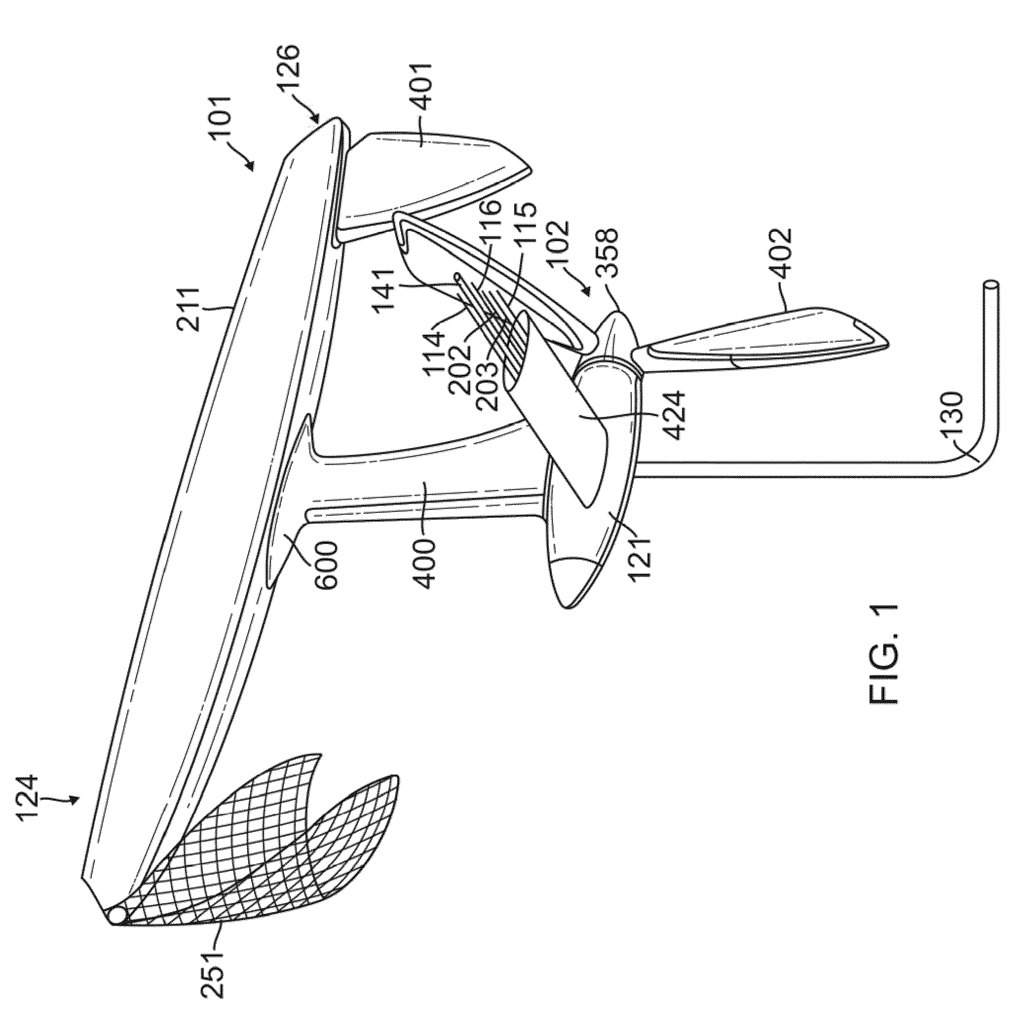
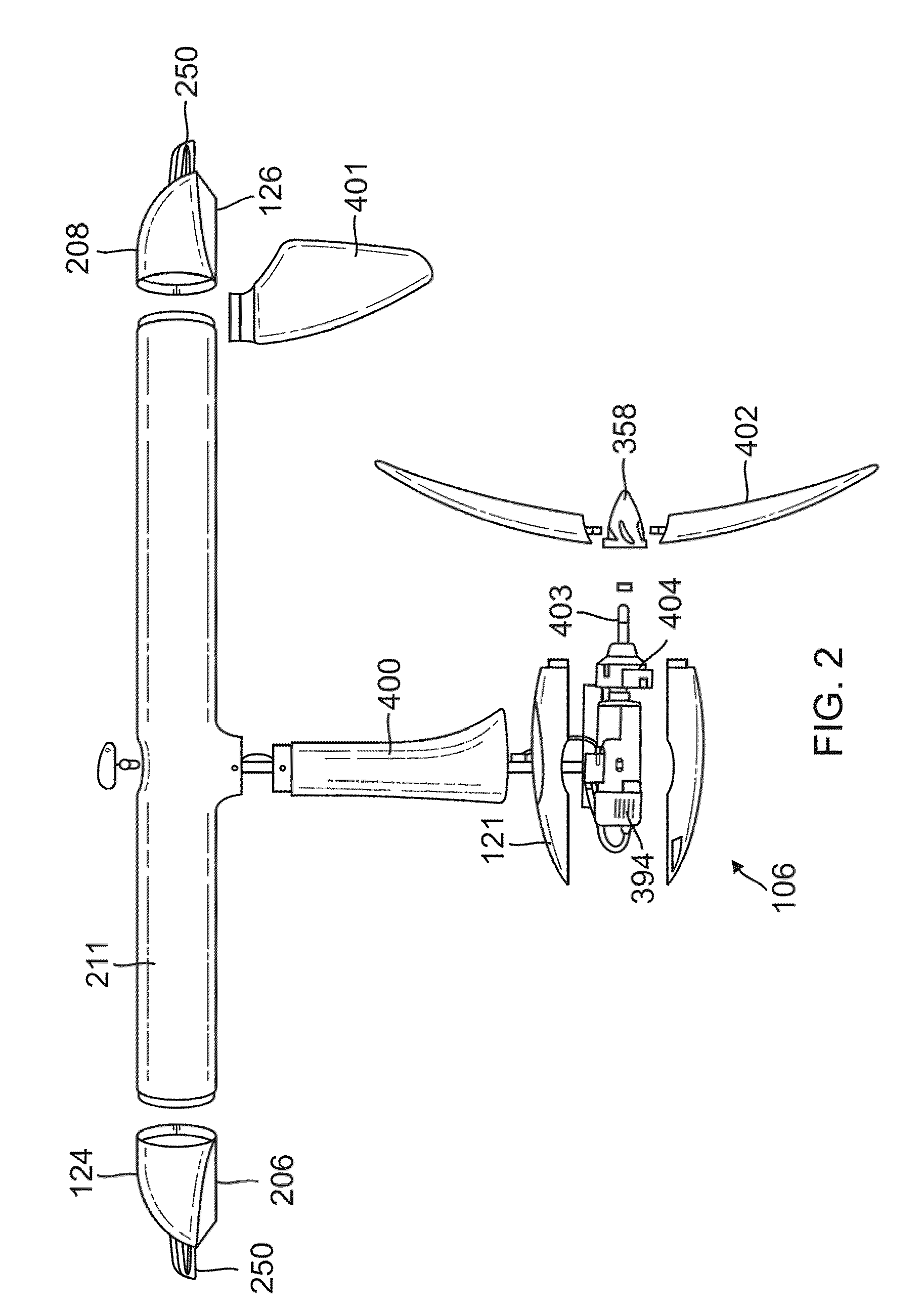
[0071]The present invention relates to a river and tidal energy generation system. The invention is of an inexpensive, rugged and mobile design that is low cost and energy efficient. An array of interconnected energy devices designed for both river and tidal flow siting are arrayed across the path of the direction of the primary current so as to absorb the largest spectrum of river current energy. The invention has a non-fouling, self-cleaning surface that repels both debris and marine growth. Its low operational speed, rounded surfaces and minimal anchor cables provides the ultimate safety for wildlife. It has a minimum number of parts to reduce costs and breakdowns as well as maximizing the use of available parts. It minimizes internal, inertial / mass, the number of energy conversion stages and surface friction to offer high overall energy conversion efficiency. It is easy to install and to remove and from its operational site and service by automated means using remote controlled ...


PUM


Abstract

An energy module comprising an energy absorber; and a mooring system, comprising a wing-shaped polymer shell attached to the energy absorber, the wing-shaped polymer shell designed to utilize the force of a passing current to create a downward force and thereby reduce any upward motion in the energy module; and a mooring cable housed inside the wing-shaped polymer shell and anchored to maintain the energy module in a fore and aft and a side-to-side position to provide stability, and to negate a rotational force on the energy module.

Description

CROSS-REFERENCE TO RELATED APPLICATIONS[0001]This patent application is a continuation-in-part of International Application No. PCT / US2007 / 022252 filed Oct. 18, 2007, which claims the benefit of priority to U.S. application Ser. No. 11 / 585,722 filed Oct. 24, 2006, which are incorporated herein by this reference.TECHNICAL FIELD[0002]This invention relates to the field of energy, specifically, to a device that can produce mechanical and electric energy from river and tidal sources with improved efficiency, minimum cost and maintenance, and without producing any greenhouse gases (GHG) emissions, directly or indirectly.BACKGROUND OF THE INVENTION[0003]The world's energy appetite is growing fast and energy production capacity is being rapidly devoured. A fundamental shift in global demand has begun accompanied by a slow supply response, given the long lead-time required to rebuild surplus fossil fuel capacity. While the major renewables, solar and wind power, are growing they still make ...

Claims


Application Information

Patent Timeline
IPC IPC(8): F03B13/00
CPCF03B13/264F03B17/061F05B2240/301F05B2240/32Y02E10/28F05B2240/917F05B2240/93F05B2270/8041F05B2270/806F05B2240/40B63B2035/4466F05B2240/9176Y02E10/30Y02A20/402Y02E10/20
Inventor CATLIN, CHRISTOPHER S.
Owner CATLIN CHRISTOPHER S
Why Eureka
Try Eureka