Electric Power Conversion Apparatus

a technology of electric power conversion and electric power, which is applied in the direction of electrical apparatus construction details, electric devices, batteries/cells, etc., can solve the problems of large heat generation in power semiconductors, limited increase in size and weight of electric power conversion apparatus, and small automobiles in general

Active Publication Date: 2009-09-17
HITACHI ASTEMO LTD
View PDF15 Cites 155 Cited by
  • Summary
  • Abstract
  • Description
  • Claims
  • Application Information

AI Technical Summary

Benefits of technology

[0030]According to a twelfth aspect of the present invention, in the electric power conversion apparatus according to the second aspect, the channel case is formed at least with a lower case and an upper case; a direct current connection member that connects terminals of the capacitor module and the semiconductor module with each other, an alternate current connection member that connects an alternate current terminal of

Problems solved by technology

While electrical energy converted by an electric power conversion apparatus tends to increase, automobiles tend to be small in size and weight in general.
Thus, increase in size and weight of an electric power conversion apparatus is limited.
When the switching action is performed, a large amount of heat is generated in the power semiconductor.
To cope with this, it is necessary to increase the size of the semiconductor chip or the number of the semiconductor chips to be used, resulting in an increase in size of the electric power conversion apparatus.
Although improvement in cooling efficiency of a semiconductor chip obviously leads to miniaturization in the semiconductor chip, it does not necessarily contribute to size reduction of the overall electric power conversion apparatus.
For instance, an improvement in cooling efficiency of a semiconductor chip may result in a complex structure of the overall electric power conversion apparatus.
Thus, although the semiconductor chip may be miniaturized, the overall electric power conversion apparatus may not be miniaturized significantly.
The electrical complexity results

Method used


Image

  • Electric Power Conversion Apparatus
  • Electric Power Conversion Apparatus
  • Electric Power Conversion Apparatus

Examples


embodiment

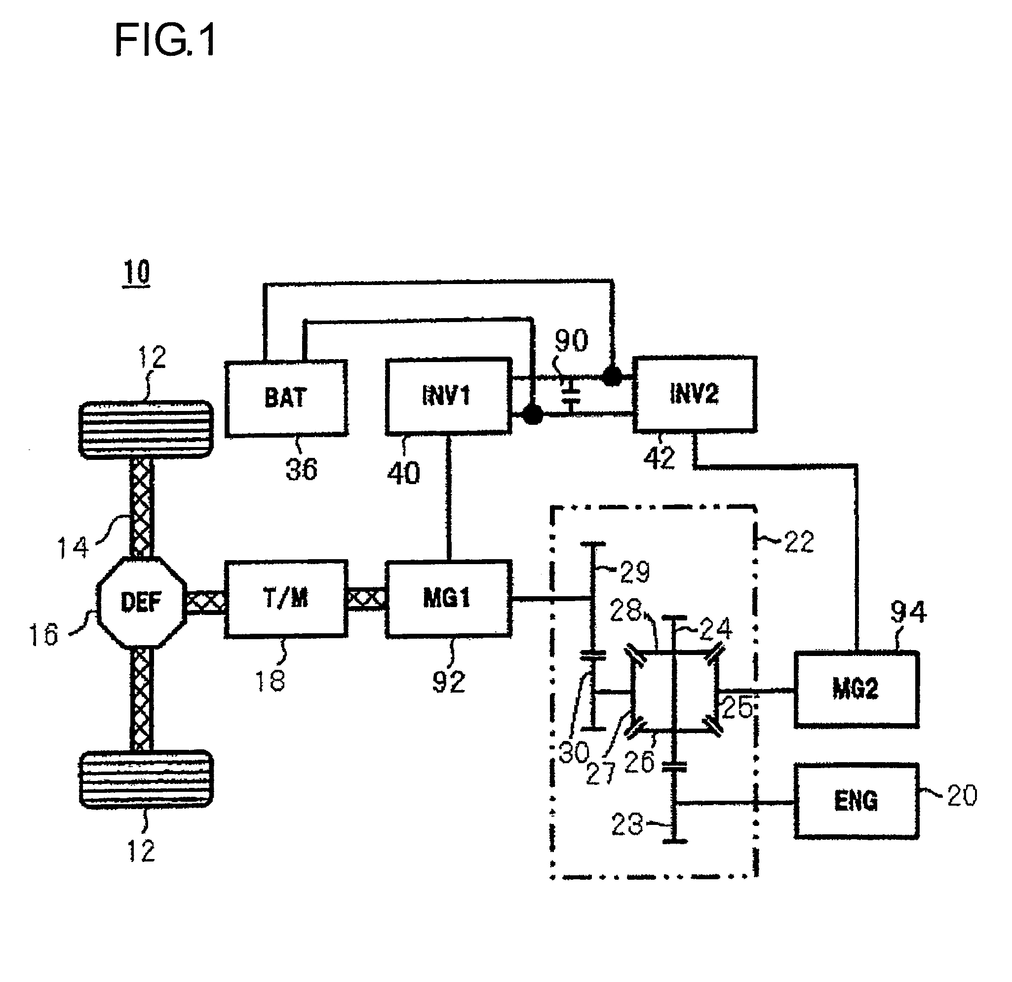
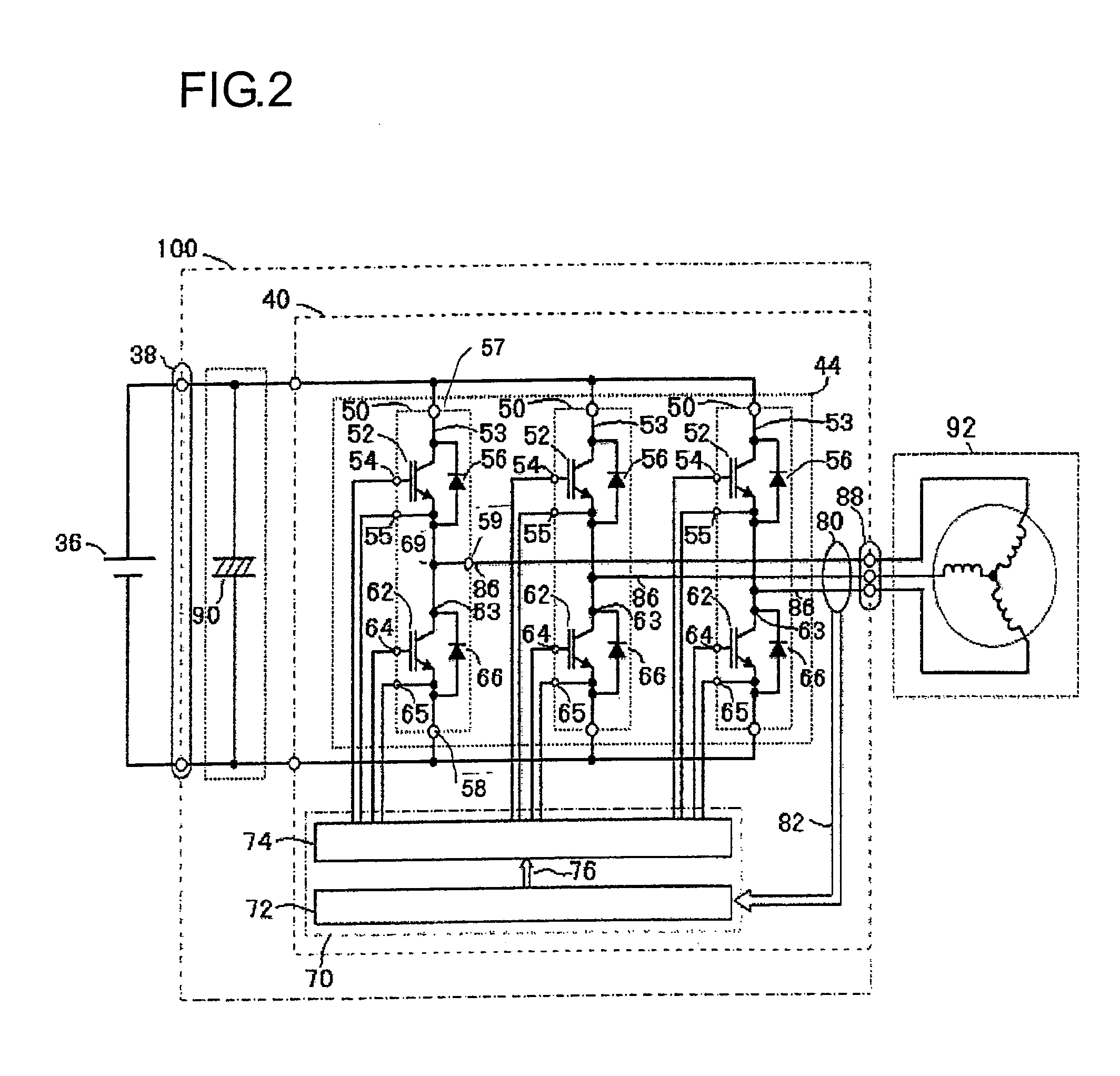
[0084]Now, referring to the attached drawings, the electric power conversion apparatus according to an embodiment of the present invention is described in detail. The electric power conversion apparatus of the embodiment present invention is applicable to hybrid automobiles and pure electric cars. A typical example of control mechanism and circuitry of the electric power conversion apparatus when the electric power conversion apparatus according to the present embodiment is applied to the hybrid automobile is described with reference to FIGS. 1 and 2. FIG. 1 is a diagram presenting a control block of a hybrid automobile. FIG. 2 is a diagram illustrating circuitry of an electric system for driving a vehicle that includes an electric power conversion apparatus constituted of an inverter device having an upper and lower arms series circuit and a capacitor connected to the upstream side of the inverter device, a battery, and a motor generator.

[0085]The electric power conversion apparatu...


PUM


Abstract

An electric power conversion apparatus includes: a channel case in which a cooling water channel is formed; a double side cooling semiconductor module that comprises an upper and lower arms series circuit of an inverter circuit; a capacitor module; a direct current connector; and an alternate current connector. The semiconductor module comprises a first and a second heat dissipation metals whose outer surfaces are heat dissipation surfaces, the upper and lower arms series circuit is disposed tightly between the first heat dissipation metal and the second heat dissipation metal, and the semiconductor module further comprises a direct current positive terminal, a direct current negative terminal, and an alternate current terminal which protrude to outside. The channel case is provided with the cooling water channel which extends from a cooling water inlet to a cooling water outlet, and a first opening which opens into the cooling water channel.

Description

INCORPORATION BY REFERENCE[0001]The disclosure of the following priority application is herein incorporated by reference:[0002]Japanese Patent Application No. 2008-061185 filed Mar. 11, 2008BACKGROUND OF THE INVENTION[0003]1. Field of the Invention[0004]The present invention relates to an electric power conversion apparatus that includes an inverter circuit.[0005]2. Description of Related Art[0006]As a conventional technology intended to increase heat dissipation efficiency of a semiconductor module by efficiently transferring heat from the semiconductor module to a cooler, patent reference literature 1 (Japanese Laid Open Patent Publication No. 2005-175163) discloses, for example, a cooling structure. According to the description of patent reference literature 1, a semiconductor module is inserted in a hole formed in a cooler for inserting a semiconductor module to allow heat to be released from a surface of the semiconductor module that abuts the hole for inserting the module. Mor...

Claims


Application Information

Patent Timeline
IPC IPC(8): H05K7/20
CPCH01L23/36H01L23/473H01L25/072H02M7/003H05K7/20927H05K1/0262H01L2924/0002H01L23/49517H01L23/3675H01L23/492H01L2924/00H01L2224/40137H01L2924/00014H01L2924/13091H01L2924/14H01L2924/181B60L50/51H01L2924/13055Y10S903/906Y10S903/907Y10S903/909Y02T10/70H01L24/40H05K7/14329H01L2224/45099H01L2224/40H01L2224/36H05K7/2089B60K6/26B60K6/28B60K6/46B60K17/16B60L15/007B60L2210/40B60L2220/14B60L2240/429B60Y2200/92H01L23/3121H01L24/45H01L2924/1203H02M7/537H02P27/06H01L2924/00012
Inventor TOKUYAMA, TAKESHINAKATSU, KINYASAITO, RYUICHIHORIUCHI, KEISUKESATOH, TOSHIYAMIYAZAKI, HIDEKI
Owner HITACHI ASTEMO LTD
Why Eureka
Try Eureka