
Wireless communication device

a communication device and wireless technology, applied in the field of radio communication equipment, can solve the problems of degrading communication quality, degrading communication quality, and ignoring corrective measures in the radio network using one channel, and achieve the effect of facilitating local frequency generation and easy control of center frequency

Active Publication Date: 2009-09-17
SONY CORP
View PDF4 Cites 12 Cited by
  • Summary
  • Abstract
  • Description
  • Claims
  • Application Information

AI Technical Summary

Benefits of technology

The Low-IF system effectively transmits and receives multiband OFDM signals with reduced DC offset and spurious signals, enabling efficient frequency hopping and power management.

Problems solved by technology

The radio network using one channel has no corrective measures when another system interrupts the communication or an interference degrades the communication quality.
An interference may degrade the communication quality when another system interrupts the communication or the number of participating stations increases to leave no allowance in the band.
The multi-path environment generates a delay distortion (or frequency selective fading) to cause a communication error.
Further, an inter-symbol interference results from the delay distortion.
Each carrier is provided with a narrow band, making it difficult to be subject to effects of the frequency selective fading.
There is a known problem that the local signal's self mixing (LO self mixing) causes a DC component, i.e., a DC offset (e.g., see non-patent document 7).
The problem is that the most time within the OFDM symbol is accompanied by the step response.
However, there is the problem that the multiband OFDM_UWB system is subject to a large difference in the channel changeover as shown in FIG. 17.
However, there may be problems concerning the circuit's planar dimension and power consumption, a frequency phase difference for each oscillator, and the like.
(1) Since two SSB mixers are needed, the circuit configuration is complicated and the power consumption is large.
(2) Since the 264 MHz frequency signal is a rectangular wave, third harmonics cause a spurious signal of approximately up to −10 dBc in group 1.

Method used


Image

  • Wireless communication device
  • Wireless communication device
  • Wireless communication device

Examples


Embodiment Construction

[0106]Embodiments of the present invention will be described in further detail with reference to the accompanying drawings.

[0107]A Low-IF system receiver is known as means to solve the DC offset problem in the direct conversion receiver. For example, the Low-IF system is described in “Low-IF Topologies for High-Performance Analog Front Ends of Fully Integrated Receivers” (IEEE Trans. Circuits Syst. II, vol. 45, pp. 269-282, March 1998)” written by J. Crols and M. Steyaert.

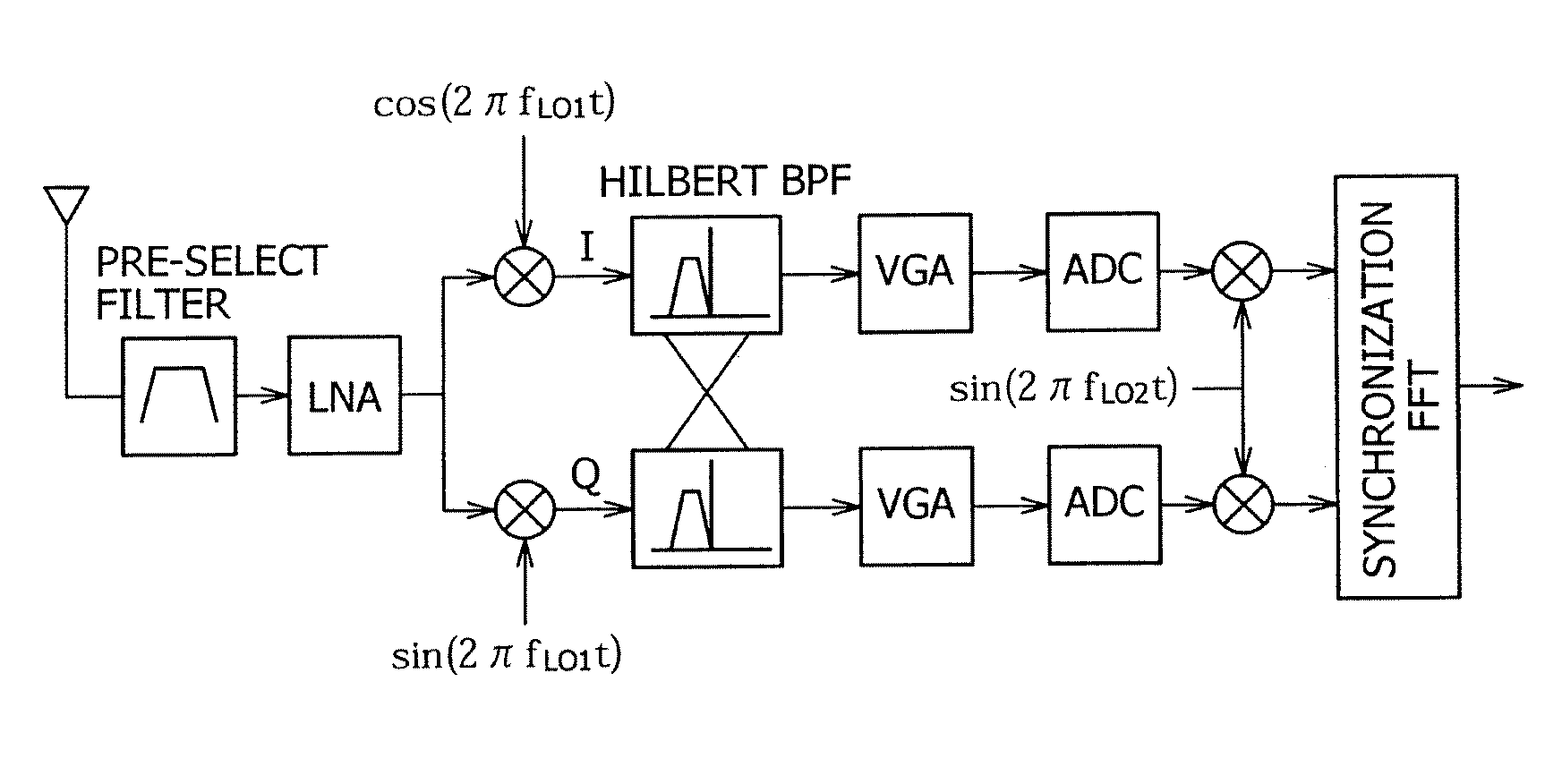
[0108]FIG. 25 shows the general configuration of the Low-IF receiver. The Low-IF receiver in FIG. 25 converts a reception signal into an intermediate frequency (IF) using first complex local signal frequencies cos(2fLO1t) and sin(2fLO1t) different from the reception frequency. During the frequency conversion, an intended signal and an image signal on both sides of local frequency LO1 appear in the IF. The Hilbert band pass filter (BPF) is used as an IF filter to remove image signals. The receiver then amplifies the...


PUM


Abstract

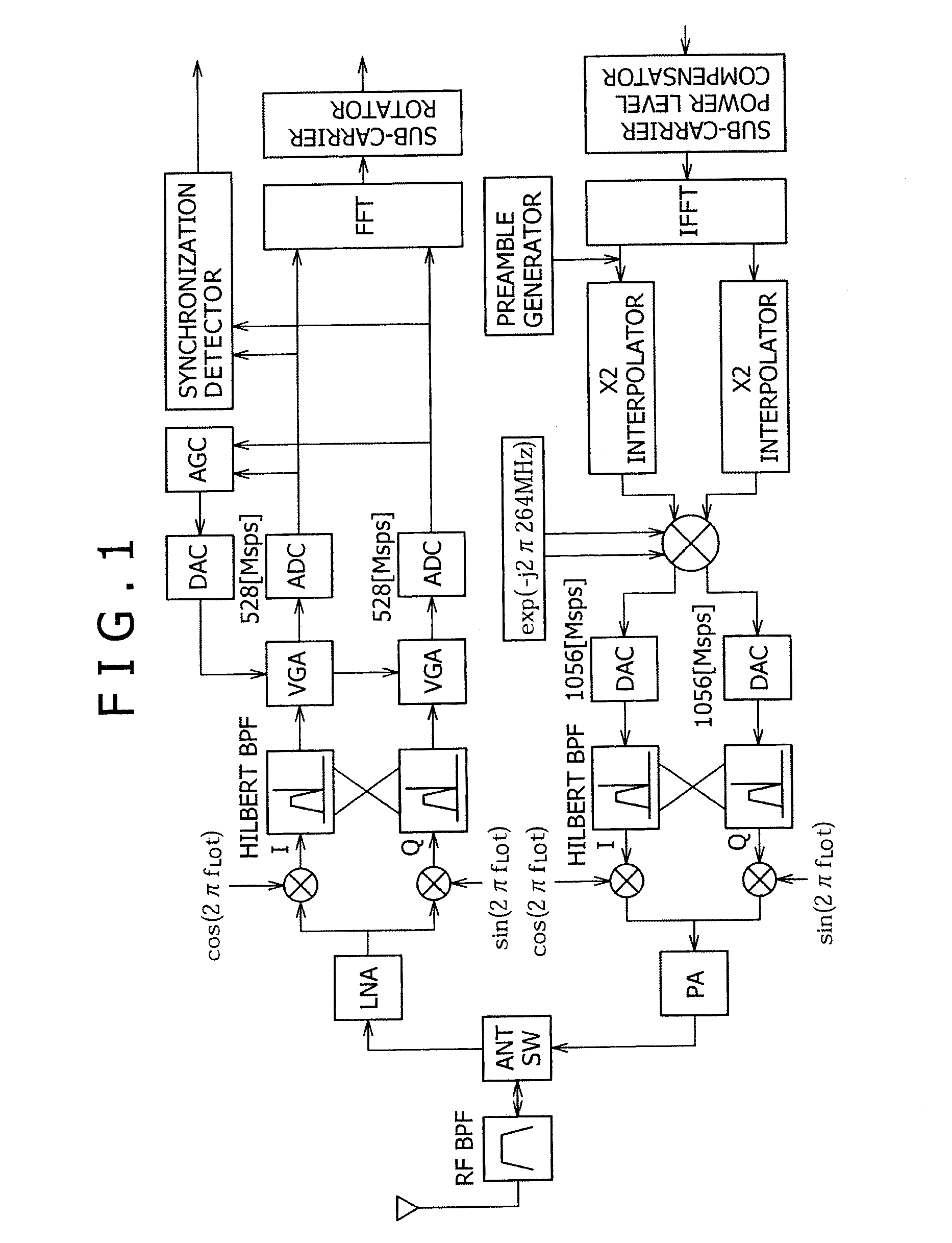
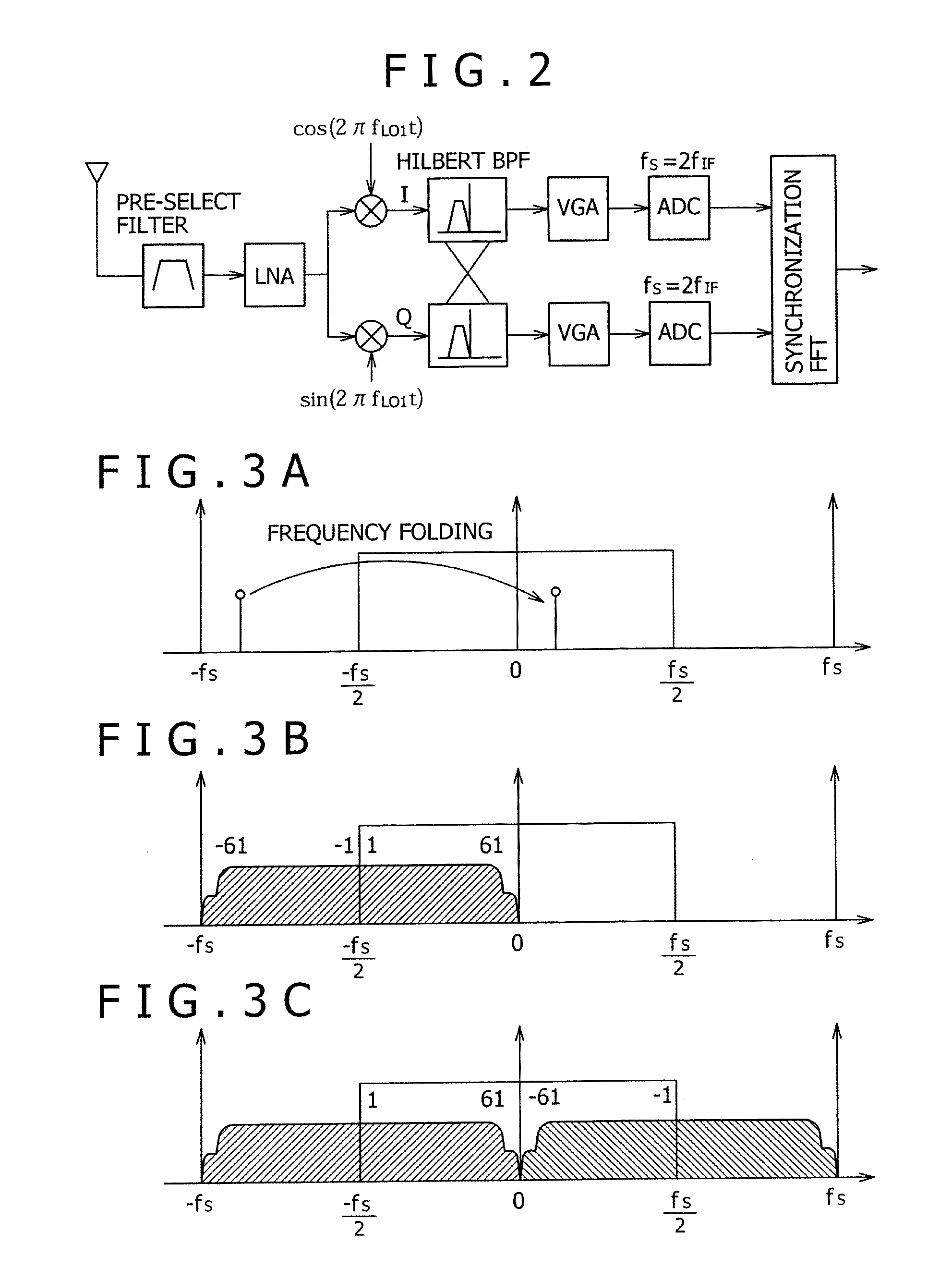
A multiband OFDM_UWB transmitting and receiving apparatus is provided in Low-IF configuration to solve problems attributed to a direct-conversion transmitting and receiving apparatus. A Low-IF receiver performs sorting by rotating a sub-carrier after FFT to eliminate the need for frequency conversion using a second local signal and uses the same AD conversion clock as that for a direct conversion receiver. An FFT-free preamble can be detected by using a sequence resulting from previously multiplying an original preamble pattern and an IF frequency together.

Description

CROSS REFERENCE TO RELATED APPLICATIONS[0001]This application is a divisional application of U.S. application Ser. No. 10 / 580,823 filed May 26, 2006, the entire contents of which are incorporated herein by reference, which is based upon and claims the benefit of priority from the prior Japanese Patent Application No. 2004-309148 filed on Oct. 25, 2004.TECHNICAL FIELD[0002]The present invention relates to a radio communication apparatus for transmitting and receiving multiband radio signals and more particularly to a radio communication apparatus for transmitting and receiving multiband OFDM signals whose center frequency hops at a specified band interval.[0003]In more detail, the present invention relates to a radio communication apparatus according to the OFDM_UWB communication system for changing frequencies in a broad band and more particularly to a radio communication apparatus according to the OFDM_UWB communication system based on the Low-Intermediate Frequency (Low-IF) archit...

Claims


Application Information

Patent Timeline
Patent Type & Authority Applications(United States)
IPC IPC(8): H04L27/12H04B7/02H04J11/00
CPCH04B1/71637H04L27/2647H04B2001/71365H04B1/719H04B1/713H04J11/00
Inventor IIDA, SACHIO
Owner SONY CORP
Learn More