Mold cooling device

a cooling device and mold technology, applied in the field of mold cooling devices, can solve the problems of increasing the temperature of the other parts, affecting the cooling efficiency of the suction pump, and the portion that is likely to receive a lot of heat, so as to prevent the suction of water vapor and increase the cooling efficiency. the effect of the durability increas

Active Publication Date: 2009-09-24
J F T
View PDF3 Cites 7 Cited by
  • Summary
  • Abstract
  • Description
  • Claims
  • Application Information

AI Technical Summary

Benefits of technology

[0016]According to the present invention, the sufficient amount of cooling water can flow to the cooling passageway of the mold to increase the cooling efficiency. In addition, the decrease in durability of the suction pump due to the suction of water vapor can be prevented.

Problems solved by technology

In particular, the protruded portion within the mold cavity, such as a core pin, is likely to receive much heat from the molten metal, and is likely to increase temperature more than the other portions.
As a result, the amount of cooling water flowing through the cooling passageway may become insufficient and the cooling efficiency may decrease.
In addition, since the agglomeration of water vapor with high temperature is sucked by the suction pump, the suction pump increases the burden and the durability of the suction pump is disadvantageously affected.
When the water vapor is sucked into the usually used suction pump, the suction pump is deteriorated due to high temperature and the suction becomes insufficient due to the pressure of the water vapor, thereby leading to the further decrease in cooling efficiency.

Method used


Image

  • Mold cooling device
  • Mold cooling device
  • Mold cooling device

Examples


Embodiment Construction

[0017]Hereinafter, embodiments of the present invention will be described.

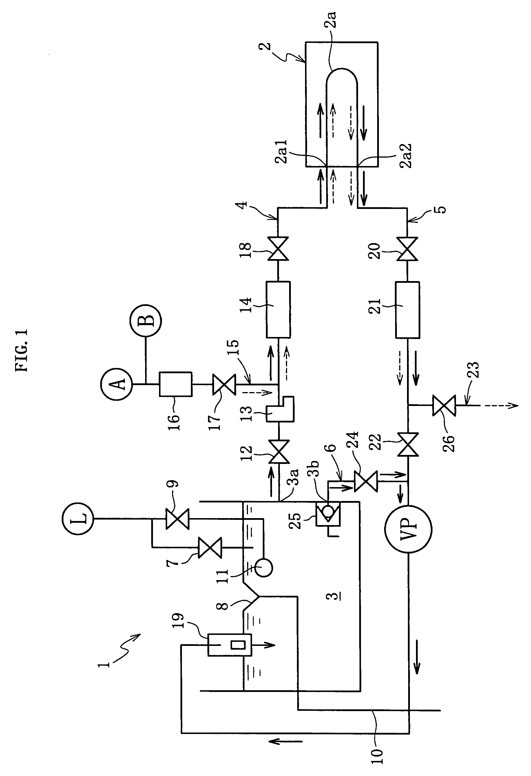
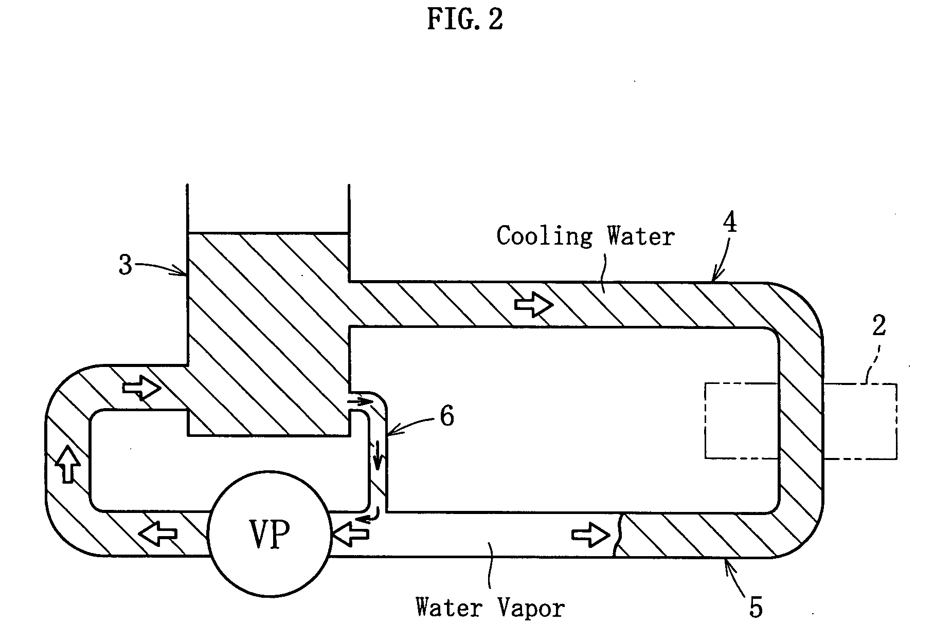
[0018]FIG. 1 shows a mold cooling device 1 according to an embodiment. The mold cooling device 1 conducts forced cooling in a mold 2 in a casting process such as die casting or the like. The mold cooling device 1 includes: a water tank 3 storing cooling water; a supply-side pipe line 4 leading from a first feed-water inlet 3a of the water tank 3 to an inlet 2a1 of a cooling passageway 2a of the mold 2; a return-side pipe line 5 leading from an outlet 2a2 of the cooling passageway 2a of the mold 2 to the water tank 3; a suction pump VP disposed in the return-side pipe line 5; and a bypass pipe line 6 leading from a second feed-water inlet 3b of the water tank 3 to the return-side pipe line 5 (the upstream location of the suction pump VP).

[0019]The cooling water is supplied to the water tank 3 via a feed-water valve 7 from a water source L such as water line. The feed-water valve 7 is closed at the time when the...


PUM

PropertyMeasurementUnit
flow rateaaaaaaaaaa
flow rateaaaaaaaaaa
pressureaaaaaaaaaa

Abstract

At the operation of a suction pump VP, a negative pressure is generated in a supply-side pipe line 4, a cooling passageway 2a of a mold 2, and a return-side pipe line 5. Cooling water stored in a water tank 3 is sucked by the negative pressure, flows from a first feed-water inlet 3a to the supply-side pipe line 4, flows through the supply-side pipe line 4, and enters the cooling passageway 2a of the mold 2. After the cooling water cools down the mold 2 while flowing through the cooling passageway 2a of the mold 2, it flows out to the return-side pipe line 5. On the other hand, at the operation of the suction pump VP, a negative pressure is also generated in a bypass pipe line 6. The cooling water stored in the water tank 3 is sucked by the negative pressure, flows from a second feed-water port 3b to the bypass pipe line 6, and enters the return-side pipe line 5 via the bypass pipe line 6.

Description

FIELD OF THE INVENTION[0001]The present invention relates to a mold cooling device for cooling a mold by supplying a cooling passageway formed in the mold with cooling water, in die casting, resin molding or the like.BACKGROUND OF THE INVENTION[0002]For example, in the casting process, such as die casting, low pressure casting, and gravity casting, the forced cooling of mold is conducted for the purpose of the stabilization of quality caused by the reductions in cycle time of the casting and the control of solidification of the molten metal injected into the mold cavity. Such forced cooling of mold is generally conducted by pumping the cooling water, pressurized by a pressure pump, into the cooling passageway of the mold (e.g., Patent Document 1).[0003]However, in the manner where the cooling water is pumped into the cooling passageway of the mold, a pressure loss occurs or a state of turbulence occurs when the cooling water flows through the piping system or the cooling passageway ...

Claims


Application Information

Patent Timeline
Patent Type & Authority Applications(United States)
IPC IPC(8): B22C9/00B22D46/00B29C33/04
CPCB22C9/065B29C35/007B22D17/2218B22C9/06B22D17/22B22D41/005B29C33/04
Inventor MINEMOTO, MASAYUKISUEKI, YOSHITAKA
Owner J F T
Why Eureka
Try Eureka