Light-emitting diode driving circuit and secondary side controller for controlling the same
a driving circuit and diode technology, applied in the direction of electric variable regulation, process and machine control, instruments, etc., can solve the problems of affecting the accuracy of dimming control, increasing and burning of these leds, so as to reduce the cost of the led driving circuit and simplify the layout of the printed circuit board. , the effect of small voltage variation
- Summary
- Abstract
- Description
- Claims
- Application Information
AI Technical Summary
Benefits of technology
Problems solved by technology
Method used
Image
Examples
first embodiment
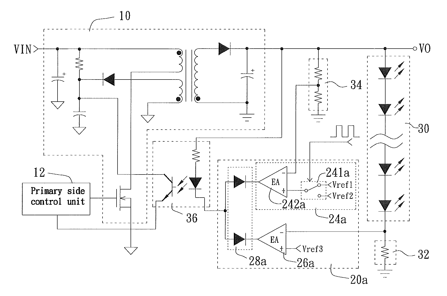
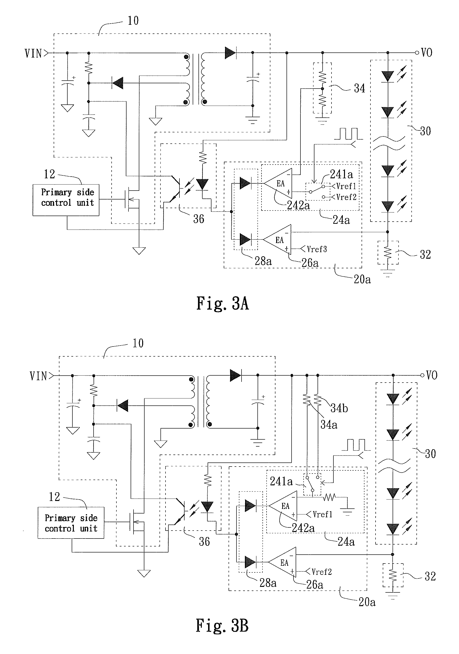
[0016]The secondary side control unit 20a includes a voltage detection signal processor 24a, a current detection signal processor 26a, and a signal selection circuit 28a. The voltage detection signal processor 24a receives the voltage detection signal and the dimming signal, and generates a voltage processing signal according to the received signals. The current detection signal processor 26a receives the current detection signal and generates a current processing signal. The signal selection circuit 28a receives the voltage processing signal and the current processing signal, and selectively outputs one of the voltage processing signal and the current processing signal, depending on the levels of the two signals. In the illustrated first embodiment, the dimming signal is a pulse signal, which is input to the voltage detection signal processor 24a for regulating the level of the voltage processing signal output by the voltage detection signal processor 24a.
[0017]The voltage detecti...
third embodiment
[0028]In the third embodiment, when the pulse signal output by the DC-to-pulse converter 281b is at a first level representing “OFF”, the signal selector 283b outputs the voltage detection signal. Therefore, the LED driving circuit operates in the constant voltage mode, and the output voltage drops to approximately the threshold voltage of the LED module 30. At this point, the LED module 30 is close to not emitting light. On the other hand, when the pulse signal selected and output by the DC-to-pulse converter 281b is at a second level representing “ON”, the signal selector 283b selects to output the current detection signal. Therefore, the LED driving circuit operates in the constant current mode, the output voltage rises for the current flowing through the LED module 30 to stably maintain at a preset current value, and the LED module 30 emits light stably.
[0029]As having been mentioned above, the present invention may be implemented by switching between a constant current and a mi...
fourth embodiment
[0030]In the fourth embodiment, when the dimming signal DIM is at a first level representing “OFF”, the signal selector 28c selects to output the minimum duty cycle signal. Through the properly set minimum duty cycle, the control signal output by the primary side control unit 12c according to the minimum duty cycle signal has a very small duty cycle, so that the energy transmitted from the conversion circuit 10 to the secondary side is approximately sufficient for maintaining the basic energy loss by the circuit elements other than the LED module 30. In other words, the driving voltage stops dropping when it is approximately the threshold voltage of the LED module 30, and maintains around a voltage. At this point, the LED module 30 is close to not emitting light. On the other hand, when the dimming signal DIM is at a second level representing “ON”, the signal selector 28c selects to output the current detection signal. Therefore, the LED driving circuit operates in the constant curr...
PUM
 Abstract
Description
Claims
Application Information
 - R&D
- Intellectual Property
- Life Sciences
- Materials
- Tech Scout
- Unparalleled Data Quality
- Higher Quality Content
- 60% Fewer Hallucinations
Browse by: Latest US Patents, China's latest patents, Technical Efficacy Thesaurus, Application Domain, Technology Topic, Popular Technical Reports.
© 2025 PatSnap. All rights reserved.Legal|Privacy policy|Modern Slavery Act Transparency Statement|Sitemap|About US| Contact US: help@patsnap.com


