Radiation imaging apparatus

Inactive Publication Date: 2009-09-24
SHIMADZU CORP
View PDF6 Cites 19 Cited by
  • Summary
  • Abstract
  • Description
  • Claims
  • Application Information

AI Technical Summary

Benefits of technology

[0030](Effect of claim 1) It should be recognized that the spatial frequency of the scattered radiation distribution is generally lower than the spatial frequency of the direct radiation, that is, the spatial frequency of the radiation absorption distribution of a subject, and the distribution of the scattered radiation can be estimated using only the image signals of the shielded pixel column even if the radiation shielding plate is arranged at a larger pitch compared to the pixel pitch. With the above-described effects, the present invention can estimate the scattered radiation while sufficiently ensuring the transmissivity of the direct radiation by a few radiation shielding plates, and furthermore, suppress the lack of image information by the shade of the radiation shielding plate and interpolate the lacking portion, so that a clear diagnosis image sufficiently removed with the scattered radiation can be obtained. Moreover, low dose photographing becomes possible, and the exposure dose of the subject can be greatly reduced.
[0031]The 
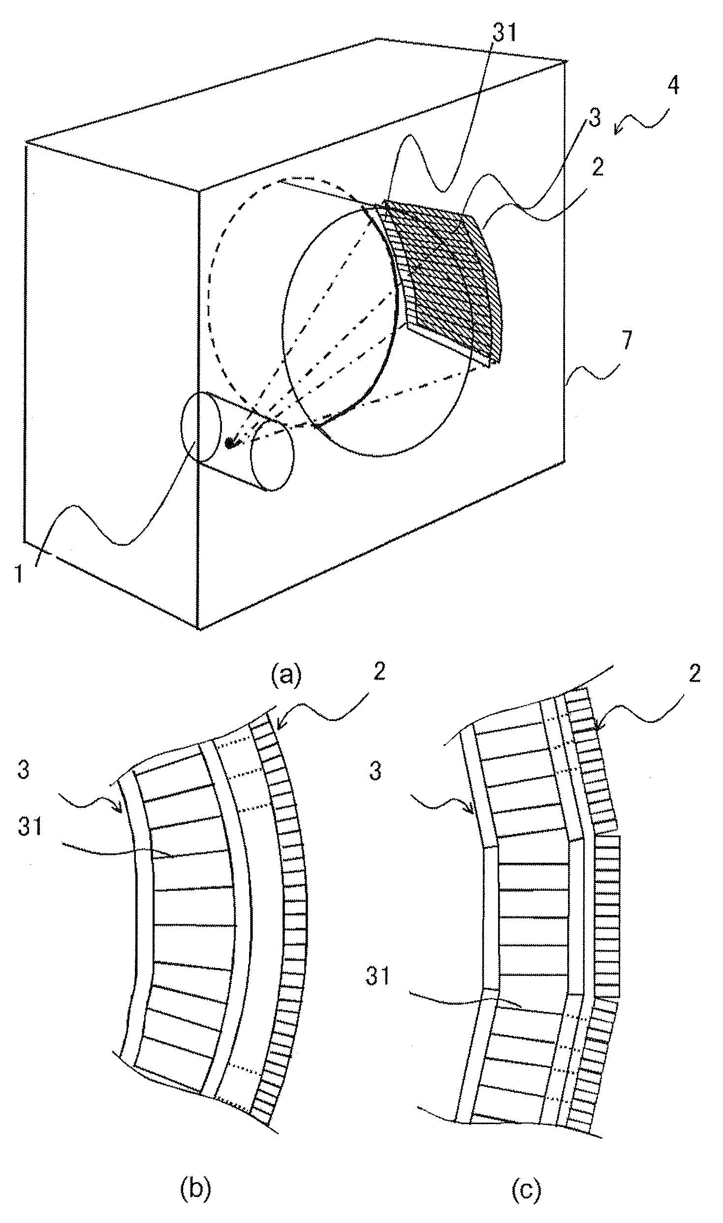
estimation of the scattered radiation and the interpolation process of the image signals in the shielded pixel column are possible with the image signals of the pixel column of a few adjacent columns. Therefore, when arranging the pixel column and the radiation shielding plate 31 in parallel, for example by storing the necessary amount of image signals in the buffer, the estimating process of the scattered radiation from the stored image signals of a plurality of columns and the interpolation process of the lacking portions of the image information can be performed simultaneously and concurrently with the reading of the image signals, whereby higher speed processing can be realized. For instance, the moving image process can be realized in real time.
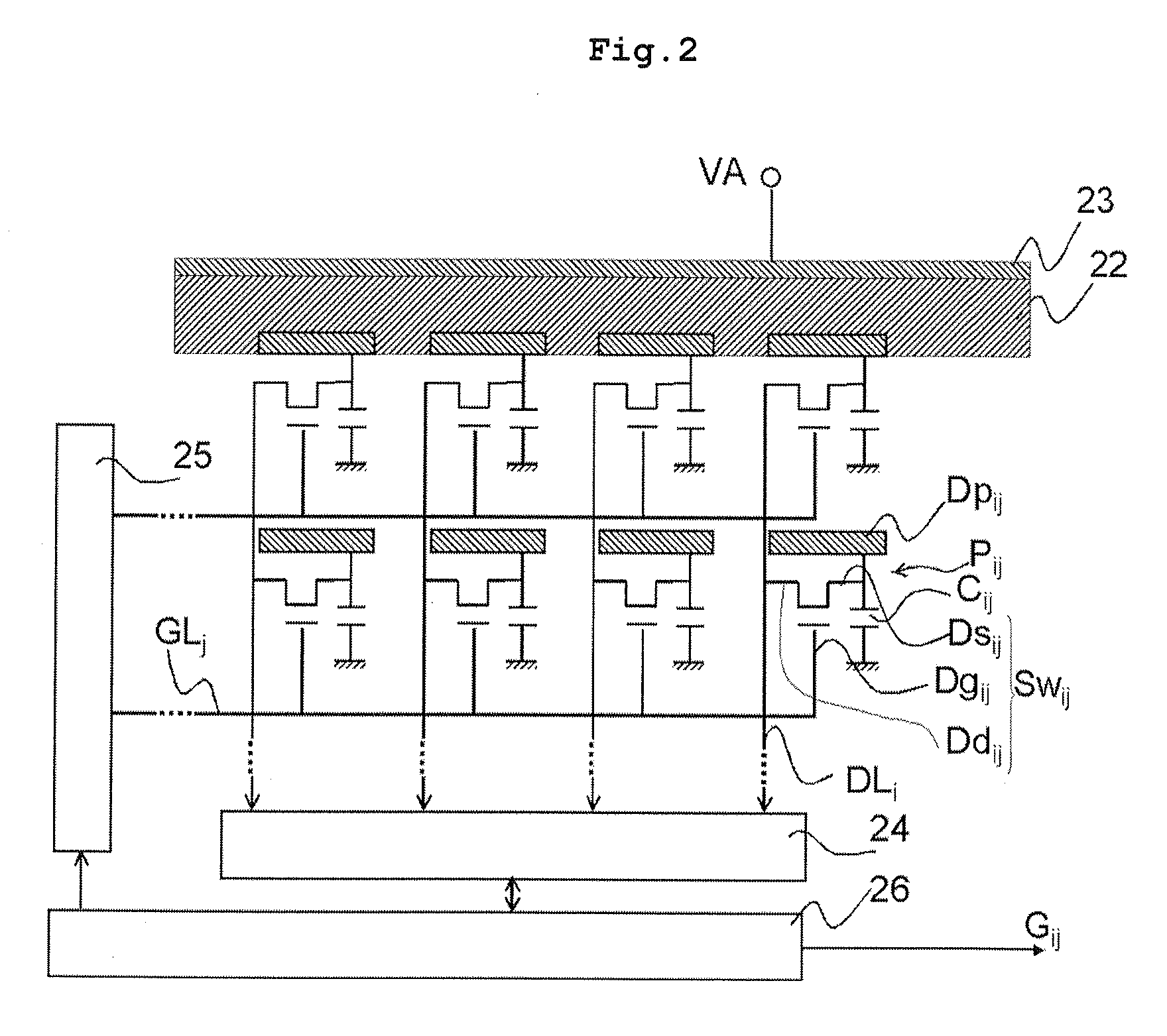
[0032](Effect of claim 11 and 19) Furthermore, by arranging the radiation shielding plate in parallel to the data line, the pixel column may be arranged in parallel to the data line and the radiation shielding plate may be arranged in parallel to each other, so that the interpolation process can be performed for each column, and the capacity of the buffer can be reduced. In this case, however, the pixels cannot be analog bound.
[0033](Effect of claims 3, 10, and 18) If the plurality of adjacent pixel columns is bound at the signal level, the resolution lowers but the process can be performed at high speeds since pixel binding is unnecessary Furthermore, the number of the radiation shielding plates to be arranged can be reduced, and the absorptance of the direct radiation can also be reduced, thereby contributing to low dose imaging. A configuration of binding only the shielded pixel columns may be adopted.
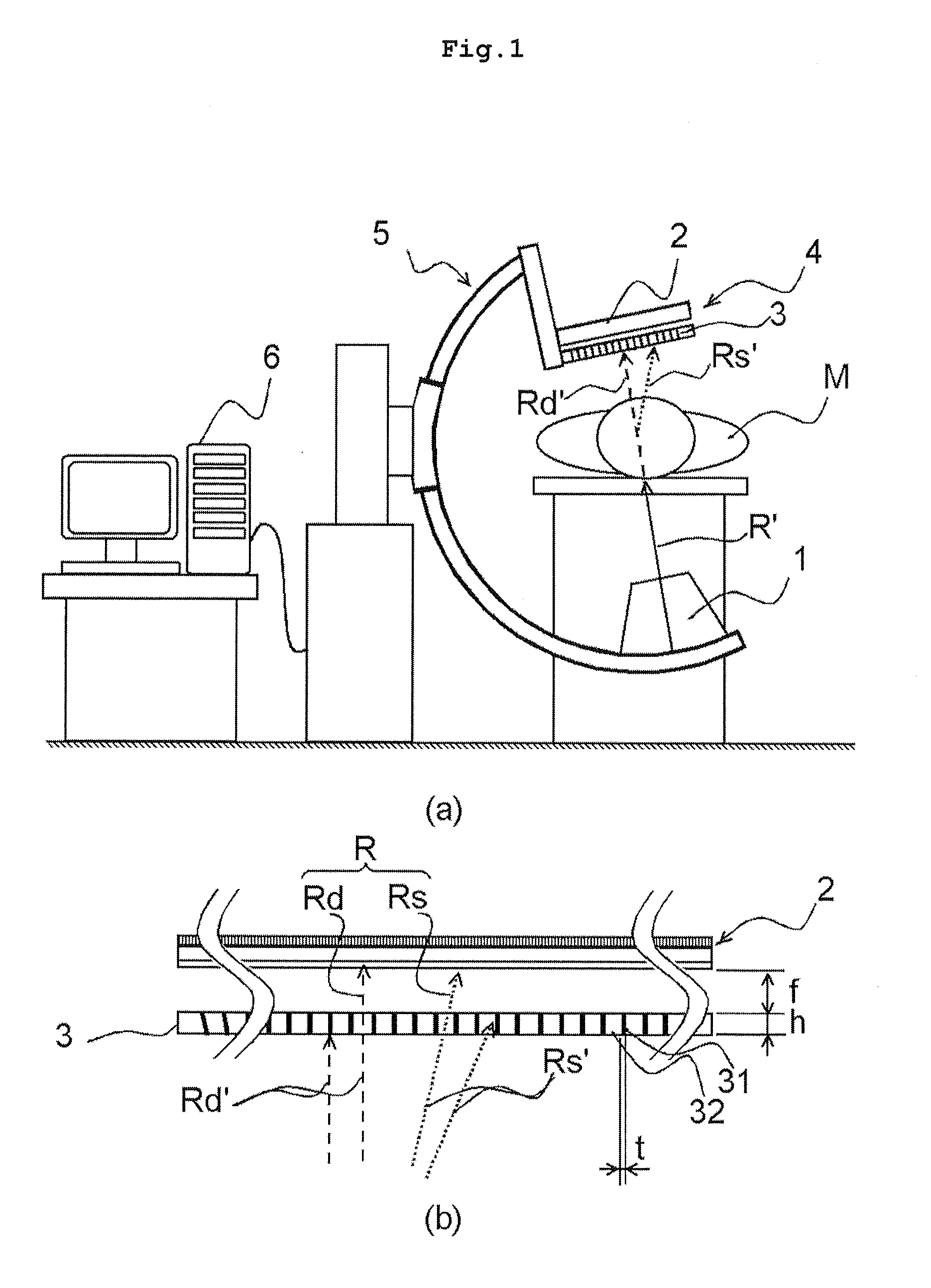
[0034](Effect of claims 4 and 12) In the scattered radiation estimating process, the calculation needs to be performed in view of the spatial direct radiation transmissivity data if the absorptance with respect to the scattered radiation of the anti-scatter grid is not spatially even. However, if the distance between the anti-scatter grid and the detector is an integral multiple of the height of the radiation shielding plate, the calculation can be simplified and high speed scattered radiation estimating process calculation can be performed.
[0035](Effect of claims 6 and 14) Even if the positions of the radiation irradiating means and the two-dimensional radiation detection means change based on the function of the apparatus, an appropriate scattered radiation estimating process calculation can be performed based on the transmitting characteristics and the like of the anti-scatter grid acquired by the shielded pixel column specifying means at each position. Specifically in an apparatus where the distance of the radiation irradiating means and the two-dimensional radiation detection means changes, even if the position and the width of the shielded pixel column change according to the distance, the position and the width of the shielded pixel column at each position can be specified in advance, and thus the estimating process calculation of the scattered radiation can be performed at the specified position of the shielded pixel column.

Problems solved by technology

However, a problem that the absorptance of the direct radiation Rd′ becomes higher arises if the pitch of the radiation shielding plate 31 is made smaller or the thickness is made thicker.

Method used


Image

  • Radiation imaging apparatus
  • Radiation imaging apparatus
  • Radiation imaging apparatus

Examples


Embodiment Construction

[0108]An overall configuration of a radiation imaging apparatus according to the present invention will be described with reference to FIG. 1. As shown in FIG. 1, the radiation imaging apparatus according to the present invention is configured by a radiation source 1 for applying radiation on a subject M, an image receiving means 4 including a two-dimensional radiation detector 2 for detecting transmitted radiation R of the subject M and converting the same to an image signals Gij (i is a subscript indicating the direction where the data lines are lined, and j is a subscript indicating the direction where the gate lines are lined. These are the same for other reference numerals below) and an anti-scatter grid 3 arranged on a front face of the two-dimensional radiation detector 2, a video system 5 for holding the radiation source 1 and the image receiving means 4 so as to face each other with a predetermined spacing, and an image processing device 6 for performing a predetermined cor...


PUM


Abstract

A grid 3 arranged with a scattered radiation shielding plate 31 for each column is arranged at a front face of a radiation detector 2. The distance between the grid 3 and the radiation detector 2 is desirably a integral multiple of the height of the scattered radiation shielding plate 31. A true image signal of the pixel column including the shade is estimated from the image signal of the pixel column adjacent to the pixel column including the shade 41. The scattered radiation distribution is estimated from the image signals of the pixel column including the shade of the scattered radiation shielding plate and the image signals when considering that the shielding plate is not included in the shielded pixel. A clear diagnosis image without influence of scattered radiation is obtained by subtracting the estimated scattered radiation distribution from the estimated image signal distribution.

Description

TECHNICAL FIELD[0001]The present invention relates to a radiation imaging apparatus including a two-dimensional radiation detector for detecting a transmission image of radiation such as X-rays, and an anti-scatter grid for removing the scattered radiation from the transmission image.BACKGROUND ART[0002]An overall configuration of a conventional radiation imaging apparatus will be described with reference to FIG. 11.[0003]FIG. 11(a) is a general embodiment of the conventional radiation imaging apparatus. The conventional radiation imaging apparatus is configured by a radiation source 1 for irradiating on a subject M, an image receiving means 4 including a two-dimensional radiation detector 2 for detecting transmitted radiation R of the subject M and converting the same to image signals and an anti-scatter grid 3 arranged on a front face of the two-dimensional radiation detector 2, a video system 5 formed by holding the radiation source 1 and the image receiving means 4 so as to face...

Claims


Application Information

Patent Timeline
IPC IPC(8): H05G1/60G21K1/00
CPCA61B6/032A61B6/06A61B6/4291A61B6/4441A61B6/583A61B6/4233A61B6/03G01T7/00
Inventor OIKAWA, SHIRO
Owner SHIMADZU CORP
Why Eureka
Try Eureka