Vacuum deposition apparatus and control method thereof

Inactive Publication Date: 2009-09-24
SAMSUNG ELECTRO MECHANICS CO LTD
View PDF9 Cites 7 Cited by
  • Summary
  • Abstract
  • Description
  • Claims
  • Application Information

AI Technical Summary

Benefits of technology

[0033]As set forth above, the vacuum deposition apparatus and the control method thereof according to the invention can form very precise internal electrodes of chip components in a roll-to-roll chip manufacturing process by forming the internal electrode patterns at a high speed and feeding the film web to be substantially synchronized with the mask through correct tension adjustment.

Problems solved by technology

However, the thickness of the internal electrode layers can be reduced in a relatively smaller amount than the thickness of the dielectric layers because it is difficult to improve some factors of metal nano-particles of the internal electrode layers such as size, geometry and physical properties.

Method used


Image

  • Vacuum deposition apparatus and control method thereof
  • Vacuum deposition apparatus and control method thereof
  • Vacuum deposition apparatus and control method thereof

Examples


Embodiment Construction

[0038]Hereinafter, a vacuum deposition apparatus and a control method thereof according to the present invention will be described more fully with reference to the accompanying drawings, in which exemplary embodiments thereof are shown.

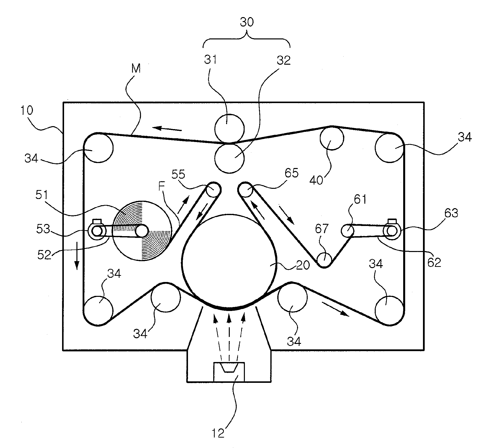
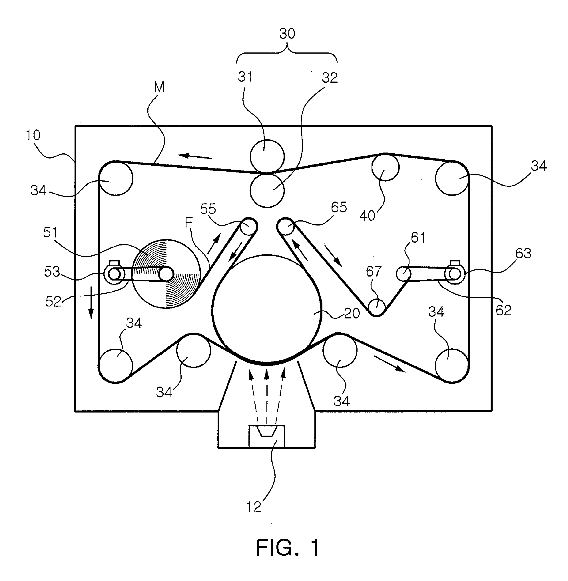
[0039]Firstly, a vacuum deposition apparatus according to an embodiment of the present invention will be described in detail with reference to FIG. 1, which schematically illustrates the vacuum deposition apparatus of the present invention.

[0040]As shown in FIG. 1, the vacuum deposition apparatus according to an embodiment of the present invention includes a chamber 10, a mask-feeding unit, a film-feeding unit and a tension-adjusting unit.

[0041]A thin film source unit 12 provided in the chamber 10 acts to apply a source of metal thin film (hereinafter, referred to as “thin film source”) including metal particles on a closely stacked structure of a film web F and a mask M, which is traveling inside the chamber 10, so that the thin film source forms a p...


PUM

PropertyMeasurementUnit
Forceaaaaaaaaaa
Ratioaaaaaaaaaa
Speedaaaaaaaaaa

Abstract

A vacuum deposition apparatus and a control method thereof can form very precise internal electrode patterns at a very high rate in a roll-to-roll manufacturing process, which is used for mass production of chip components such as a Multi-Layer Ceramic Capacitor (MLCC).

Description

CROSS-REFERENCE TO RELATED APPLICATIONS[0001]This application claims the priority of Korean Patent Application No. 2008-0027059, filed on Mar. 24, 2008 in the Korean Intellectual Property Office, the disclosure of which is incorporated herein by reference.BACKGROUND OF THE INVENTION[0002]1. Field of the Invention[0003]The present invention relates to a vacuum deposition apparatus and a control method thereof, and more particularly, to a vacuum deposition apparatus, which can form precise internal electrode patterns in a roll-to-roll manufacturing process of chip components, and a control method thereof.[0004]2. Description of the Related Art[0005]In general, chip components such as a Multi-Layer Ceramic Capacitor (MLCC) and a chip inductor are manufactured by stacking a plurality of ceramic sheets, on which internal electrode patterns are formed, and then performing a series of processes on the stack of the ceramic sheets.[0006]These chip components are required to have small size a...

Claims


Application Information

Patent Timeline
IPC IPC(8): C23C16/52C23C16/04H01G13/00
CPCH01G4/005H01G13/00H01G4/30C23C14/24C23C14/56C23C14/04
Inventor LEE, YOUNG WOOKIM, GEE LYONGCHO, JEONG MIN
Owner SAMSUNG ELECTRO MECHANICS CO LTD
Why Eureka
Try Eureka