Digital Ultrasound Beam Former with Flexible Channel and Frequency Range Reconfiguration

a beam former and flexible technology, applied in the field of ultrasound imaging methods and instruments, can solve the problems of increasing the cost of the beam former per channel, hence the required number of bits, and increasing the center frequency and bandwidth further reducing the dynamic range of the signal, so as to increase the effective sampling rate, increase the sampling rate, and increase the effect of digital dynamic rang

Inactive Publication Date: 2009-09-24
SURF TECH AS
View PDF5 Cites 29 Cited by
  • Summary
  • Abstract
  • Description
  • Claims
  • Application Information

AI Technical Summary

Benefits of technology

[0023]The digital dynamic range can be increased when groups of ADCs are connected to the same analog channel, where the outputs of ADCs with the same sample points for each analog channel are added. Where there is a delay between the sample points of the ADCs within each subgroup of ADCs to increase the effective sampling rate for each analog channel one can with lower signal bandwidths with increased sampling rates (over sampling), perform digital low pass filtering of the signals that increases the number of bits per analog channel and reduces the sampling rate.

Problems solved by technology

The cost of the beam former per channel is dominated by the cost of the ADCs, which increases with number of bits and maximal sampling frequency of the ADC.
Non-cardiac imaging requires less dynamic range and number of bits in the ADCs, and an increase in the center frequency and the bandwidth further reduces the dynamic range in the signal and hence the required number of bits.
Manufacturing technology gives a limitation on the lowest pitch of the array elements, where λ / 2 pitches are achievable for frequencies up to ˜10 MHz with current transducer array technology.

Method used


Image

  • Digital Ultrasound Beam Former with Flexible Channel and Frequency Range Reconfiguration
  • Digital Ultrasound Beam Former with Flexible Channel and Frequency Range Reconfiguration
  • Digital Ultrasound Beam Former with Flexible Channel and Frequency Range Reconfiguration

Examples


Embodiment Construction

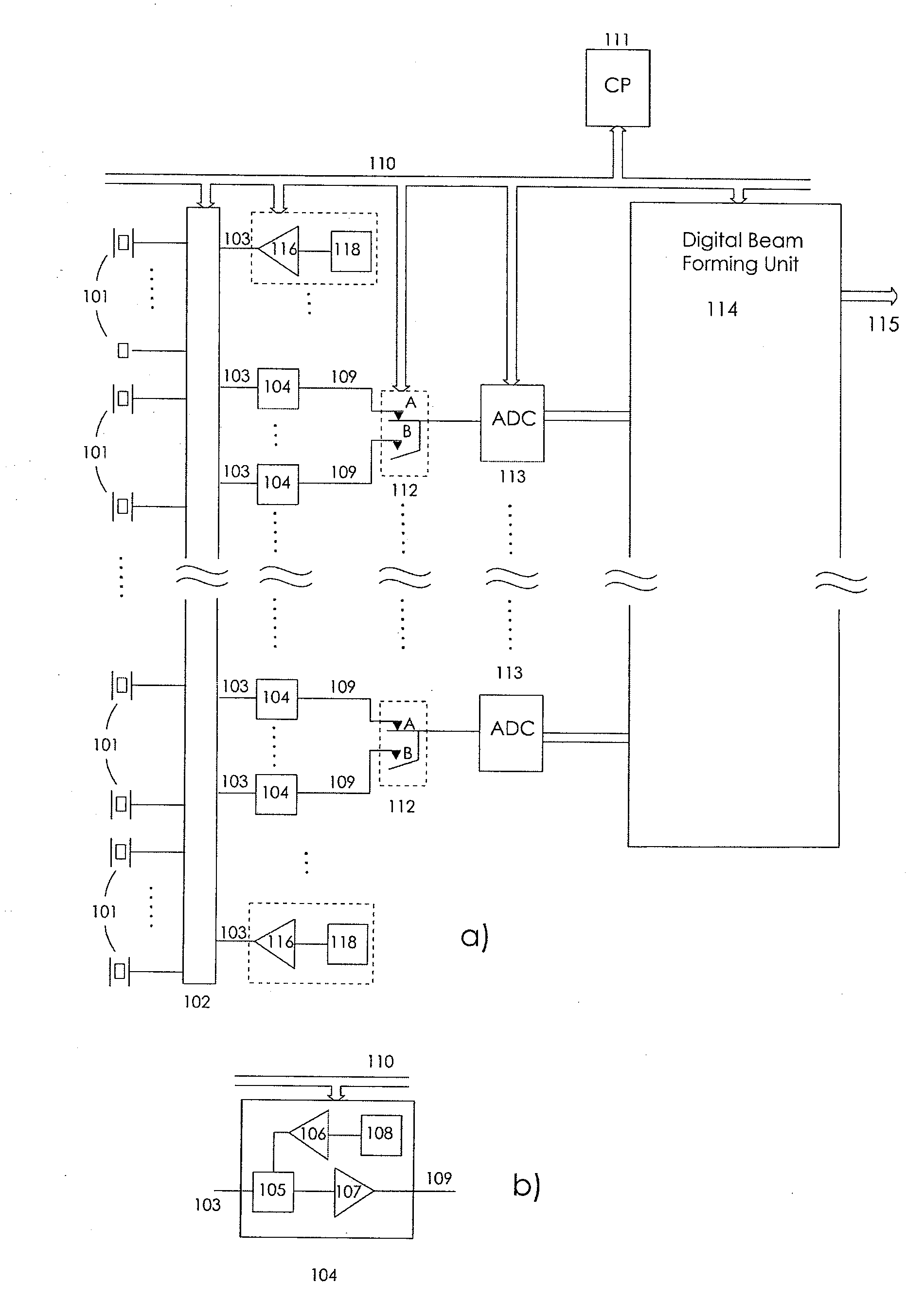
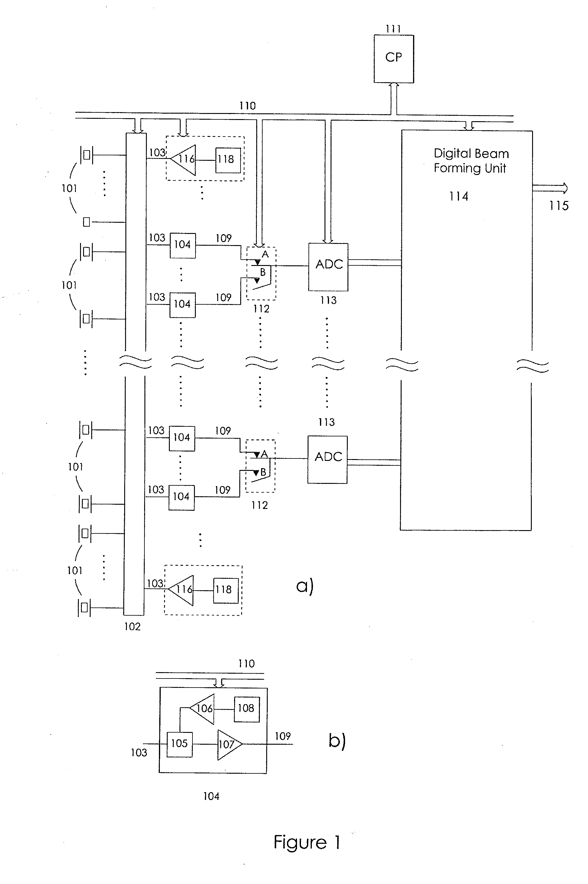
[0028]FIG. 1 illustrates one embodiment in the general spirit of the invention, where 101 indicates elements in an ultrasound transducer array or sub aperture groups of elements of the array with sub aperture beam forming circuits that present their outputs to the beam former from groups of elements, according to known methods. The elements or sub-aperture groups of elements are represented by analog channels, where all the analog channels are connected to an array coupling means 102, that provides selectable connection of the analog channels to the front connections 103 of transmitters 116 and / or combined transmitters and receivers 104. The array coupling means 102 is composed of both a probe connector that couples the analog channels to the instrument and in some embodiments also analog multiplexers or relays that participate in the selection of coupling analog channels to the transmitter and receiver amplifiers.

[0029]FIG. 1b shows an example composition of combined transmitters a...


PUM


Abstract

A digital ultrasound beam former for ultrasound imaging, that can be configured by a control processor to process the signals from ultrasound transducer arrays with variable number of elements at variable sampling frequencies, where the lowest sampling frequency allows for the highest number of array elements. The maximal number of array elements is reduced in the inverse proportion to the sampling frequency. The beam former can be operated both in a RF-sampling mode and a quadrature mode. Parallel coupling of transmit/receive circuits for each element allow adaption of the receive Noise Figure and transmit drive capabilities to variations in the electrical impedance of the array elements.

Description

CROSS REFERENCE TO RELATED APPLICATIONS[0001]This application is a continuation-in-part of U.S. patent application Ser. No. 11 / 054,399 which was filed with the U.S. Patent and Trademark Office on Feb. 9, 2005. This application also claims the benefit of U.S. Provisional Application No. 61 / 119,581, filed Dec. 3, 2008. The content of both of application Ser. No. 11 / 054,399 and provisional application No. 61 / 119,581 are expressly incorporated herein by reference.BACKGROUND OF THE INVENTION1. Field of the Invention[0002]The present invention is directed to methods and instrumentation of ultrasound imaging in a wide frequency range where the digital beamformer is reconfigurable in terms of number of channels versus frequency range.2. Description of the Related Art[0003]Digital ultrasound beam formers for medical ultrasound imaging have the last decade become feasible due to improved functionality of analog to digital converters (ADCs) and digital integrated circuit technology. However, t...

Claims


Application Information

Patent Timeline
Patent Type & Authority Applications(United States)
IPC IPC(8): A61B8/02
CPCG01S7/52025G10K11/345G10K11/341G01S15/8927
Inventor ANGELSEN, BJORN A.J.JOHANSEN, TONNI F.
Owner SURF TECH AS
Why Eureka
Try Eureka