
Method for filling electrolyte into battery cell and apparatus for carrying out the method

a battery cell and electrolyte technology, applied in the direction of cell components, liquid handling, packaging goods types, etc., can solve the problems of long time required for completely exhausting the void, large number of small voids, so as to achieve the effect of further increasing the filling speed

Active Publication Date: 2009-10-01
HIBAR SYST +1
View PDF6 Cites 14 Cited by
  • Summary
  • Abstract
  • Description
  • Claims
  • Application Information

AI Technical Summary

Benefits of technology

The present invention provides a method and apparatus for filling battery cells with electrolyte. The method involves using a special design of the filling head, which includes four valves connected to different sources of different pressure levels, and a vertically movable plunger valve that can close down the lower portion of the fill head to separate the volume underneath and above. The method includes steps of establishing a sealed connection between the electrolyte injection receptacle and a connection nozzle of a fill head, opening the valve leading to high vacuum to discharge air from the interior of the battery cell, dispensing a prescribed amount of electrolyte in the upper part of the chamber, opening the valve leading to the free atmosphere, raising the shut-off plunger to let the electrolyte be sucked into the interior of the battery cell, opening the valve connected to the high pressure to push the electrolyte into the battery cell, and repeating these steps at least once for a more complete removal of gases from the battery cell and filling the prescribed volume of electrolyte. The apparatus includes a fill head with the valves and a vertically movable plunger valve. The method and apparatus provide an efficient and effective way to fill battery cells with electrolyte.

Problems solved by technology

In the battery case with the electrode assembly installed in it, a large number of small voids are formed.
However, long time is required for completely exhausting the voids.
Further, some time is required until the non-aqueous electrolyte has permeated into the electrode assembly, and it is very difficult to inject the electrolyte within a short time.
In this apparatus, however, a funnel-like member with a reservoir corresponding to the amount of the electrolyte to be injected is mounted while the top portion of the battery base with the battery element is opened, and the space inside the battery case is exhausted.
As a result, the exhausting from the voids in the electrode assembly is insufficient because of the presence of the electrolyte.
The time required and the achieved electrolyte fill level are not mentioned, but will be limited by the driving force of atmospheric pressure.
Filling according to this method can be achieved in 60 seconds, but cannot achieve maximum electrolyte fill levels.
A problem in this filling method lies in that the high pressure is maintained till the end of the filling process, wherein the small voids cannot be filled as the air cannot escape.
The battery performance is negatively influenced by the presence of voids and by the incomplete filling of the available battery space with electrolyte.
Since maximum electrolyte fill level is very important to battery performance, some companies have started to go through 2 or 3 electrolyte fill operations on their existing vacuum fillers, which involves considerable slow down in production speeds and increased parts handing.

Method used


Image

  • Method for filling electrolyte into battery cell and apparatus for carrying out the method
  • Method for filling electrolyte into battery cell and apparatus for carrying out the method
  • Method for filling electrolyte into battery cell and apparatus for carrying out the method

Examples


Embodiment Construction

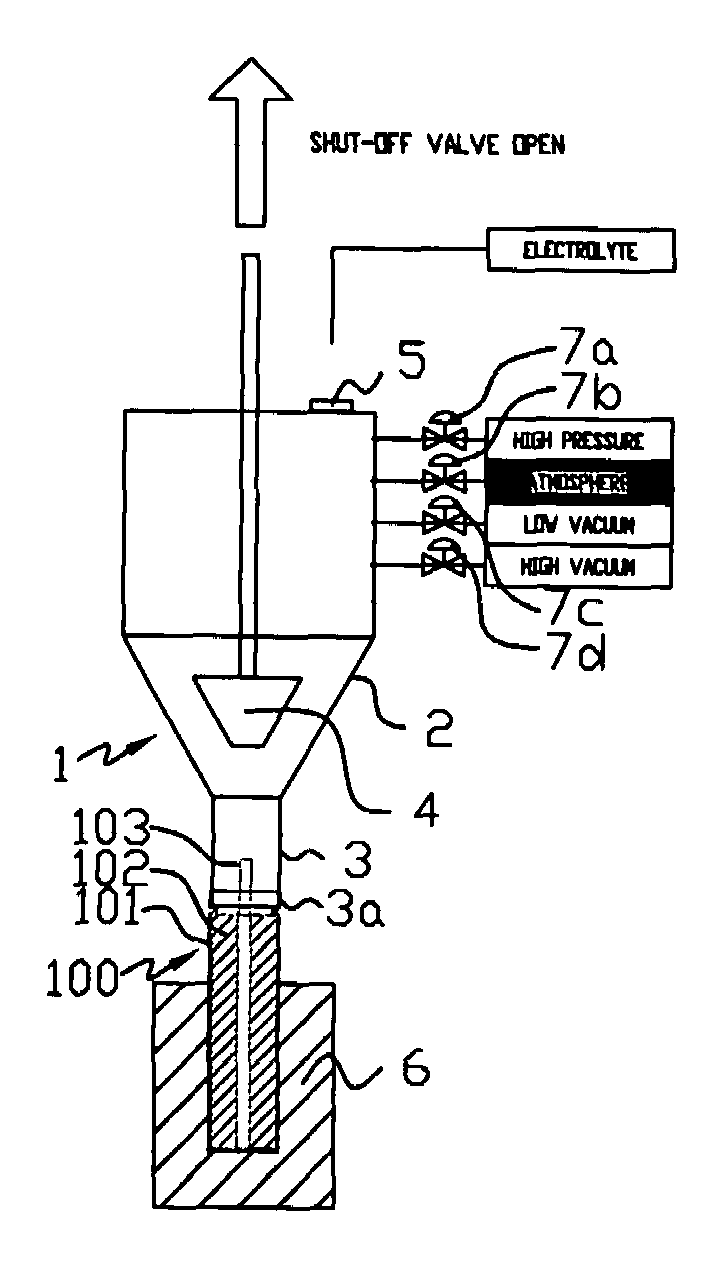
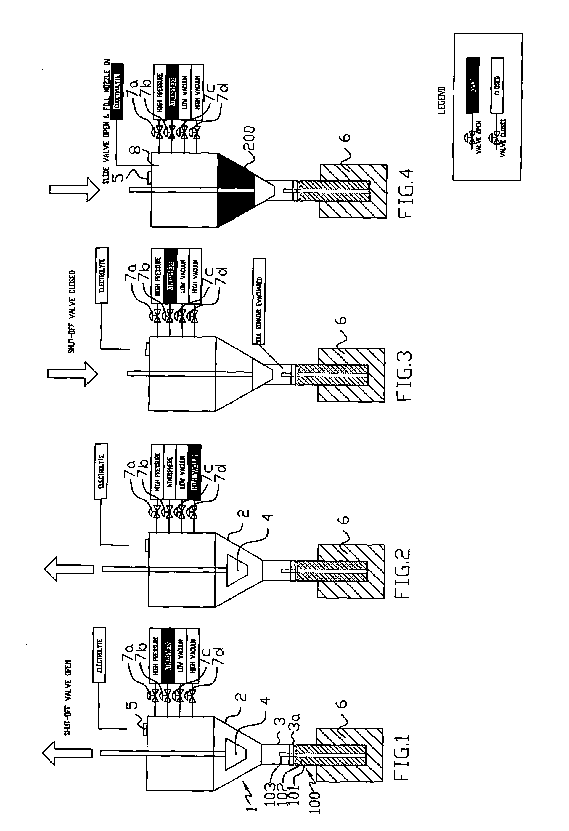
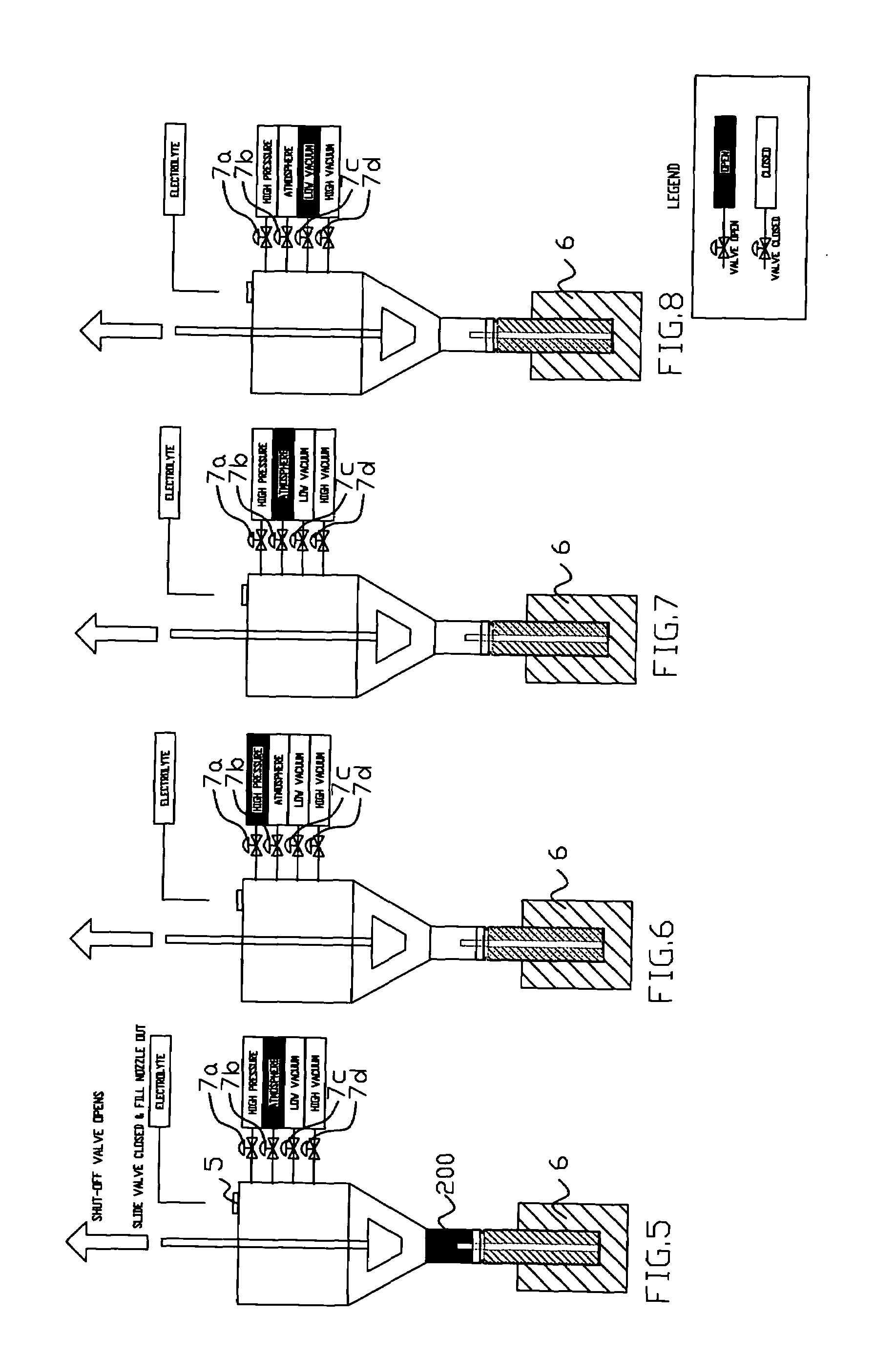
[0037]In FIGS. 1 to 8 eight discrete steps of the electrolyte filling method according to the invention has been schematically illustrated. Each of these schematic drawings show the same electrolyte fill head 1 as coupled to a battery cell 100 which is kept securely in a cell support 6. The electrolyte fill head 1 comprises a pre-metering chamber 2, a cell size specific adapter nozzle 3, an elastomer seal 3a engaging with an appropriate connection element of the battery cell 100, a shut-off plunger 4, a slider plate valve 5, an electrolyte fill port 8 with an O-ring seal around its top circumference (see FIG. 4) and four commercial pressure valves 7a-d such as SS-8BK-1C from the Swagelok company. The pressure valves 7a-d have respective first sides communicating with the interior of the pre metering chamber well above the zone of movement of the shut-off plunger 4. The other sides of the valves 7a-d are coupled to different pressure or vacuum means as illustrated by the correspondin...


PUM

PropertyMeasurementUnit
pressureaaaaaaaaaa
pressureaaaaaaaaaa
pressureaaaaaaaaaa

Abstract

A method for filling a battery cell with electrolyte, comprising:a) connecting the battery cell and a lower portion of a fill head chamber connected through respective first, second, third and fourth valves to a source of high pressure, the free atmosphere, a source of high vacuum and optionally a source of low vacuum, wherein only one of said valves can be open at any time, while said second valve is open;b) opening said third valve for a predetermined first period to discharge air from the interior of said battery cell through said chamber;c) separating the major upper portion of said chamber from the lower portion thereof by a sliding shut-off plunger and opening said second valve;d) dispensing a prescribed amount of electrolyte into said upper portion of said chamber above said plunger, while keeping said second valve open;e) raising said plunger to let a major portion of said dispensed liquid be sucked into said battery cell under the effect of the vacuum established therein in step b) and allowing any gas bubble in said battery cell to get removed through the electrolyte;f) opening said first valve for a second predetermined period to push said electrolyte into said battery cell;g) opening said second valve for a third predetermined period;h) repeating steps f) and g) at least once for the more complete removal of gases from the battery cell and filling the prescribed volume of electrolyte; and,i) disconnecting said battery cell from said fill head.

Description

FIELD OF THE INVENTION[0001]The present invention relates to a method for filling electrolyte into a battery cell, to an apparatus for carrying out the method. More particularly, the electrolyte is non-aqueous in nature and used in battery cells such as lithium ion batteries.BACKGROUND OF THE INVENTION[0002]Batteries have become increasingly popular over the last decade due to the advent of a myriad of portable electronic devices. Especially lithium ion secondary batteries have become the predominant power source for the devices such as cellular phones, notebook or laptop computers, camcorders, digital cameras and more.[0003]Lithium ion secondary batteries contain a spirally wound electrode assembly installed in a suitable battery case that has to be filled with non-aqueous electrolyte. In the battery case with the electrode assembly installed in it, a large number of small voids are formed. Typically, the air in the internal space of the battery is being drawn out by means of apply...

Claims


Application Information

Patent Timeline
Patent Type & Authority Applications(United States)
IPC IPC(8): B65B31/02B65B43/50H01M50/627
CPCH01M10/0525H01M2/361Y10T137/4757Y02E60/10H01M50/627
Inventor RESCHKE, BILL
Owner HIBAR SYST
Learn More