Ecr plasma source

a plasma source and plasma technology, applied in the direction of electrodes, chemical vapor deposition coatings, ion implantation coatings, etc., can solve the problems of increasing the cost of the coating process, limiting the possible coating time, and requiring considerable maintenance measures for the discharge area

Inactive Publication Date: 2009-10-01
ROTH & RAU MICROSYST
View PDF7 Cites 14 Cited by
  • Summary
  • Abstract
  • Description
  • Claims
  • Application Information

AI Technical Summary

Benefits of technology

[0008]The invention is therefore based on the object of providing an ECR plasma source which, in a simple manner, overcomes the disadvantages of the prior art and allows the ECR plasma source to be operated for long periods without disturbances.

Problems solved by technology

One particular disadvantage in the practical use of such plasma sources is that considerable maintenance measures are required for the discharge area.
For example, frequent cleaning of the coating system is necessary, thus considerably increasing the costs of the coating process.
This can lead to a time-dependent influence on the coating result, and restricts the possible coating times.
One frequent cause for the restriction of the coating time is conductive layers which produce short circuits in voltage or current conduction and prevent the further injection of electrical power at the coupling windows of electrodeless plasma sources.

Method used


Image

  • Ecr plasma source
  • Ecr plasma source
  • Ecr plasma source

Examples


exemplary embodiment ii

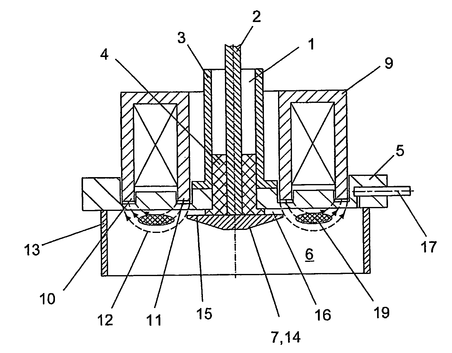
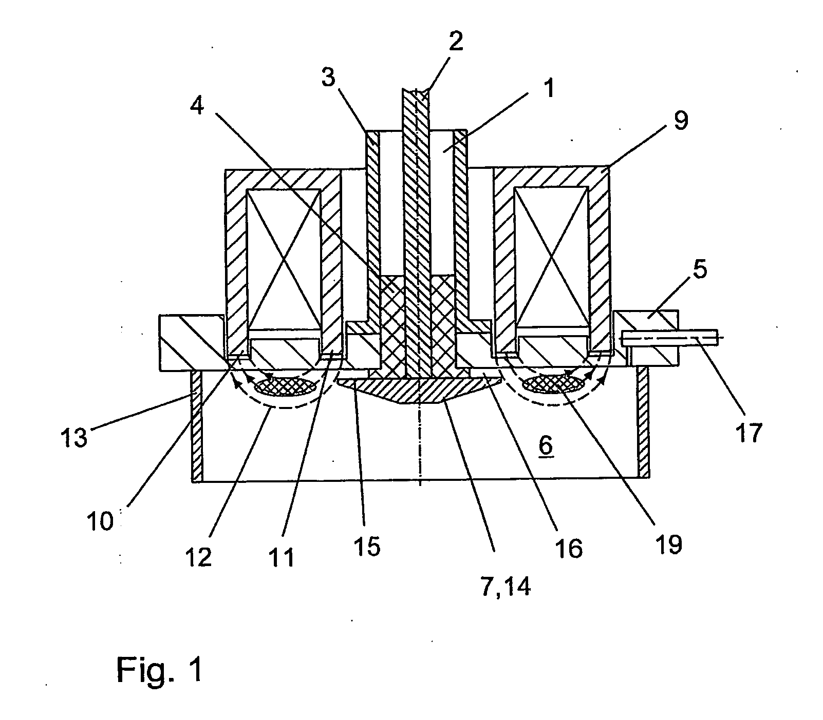
[0029]With regard to exemplary embodiment II, FIG. 3 shows a similar embodiment of the ECR plasma source to that shown in FIG. 1, but schematically in conjunction with a coating device, essentially comprising a vacuum chamber 20 having a pump connecting stub 21 and a substrate mount 22 on which substrates 23 to be treated can be positioned.

[0030]The ECR plasma source according to the invention is arranged with the plasma outlet opening 25, which corresponds to the end face of the shield 13 facing away from the vacuum flange 5, parallel to the substrate mount 22.

[0031]In addition to the bore 17 corresponding to exemplary embodiment I, a bore 24 is provided centrally in the inner conductor 2. Carrier gas and reactive gases can be supplied selectively into the vacuum chamber 20 via the two bores 17 and 24.

[0032]As in the exemplary embodiment I, the inner conductor 2 and the antenna 7 are arranged in an insulated manner in the outer conductor 3 of the microwave supply 1. An additional v...


PUM

PropertyMeasurementUnit
pressureaaaaaaaaaa
current densityaaaaaaaaaa
diameteraaaaaaaaaa

Abstract

The invention relates to an ECR plasma source comprising a coaxial microwave supply line with an internal conductor and an external conductor, wherein the internal conductor with one end as the antenna passes through a vacuum flange in insulated fashion, which vacuum flange closes off an opening in the wall to the plasma space. A multipole magnet arrangement is provided coaxially with respect to the microwave supply line and its magnetic fields pass through the vacuum flange and form an annular-gap magnetic field in the plasma space coaxially with respect to the antenna. The antenna protrudes directly into the plasma space and, in comparison with the internal conductor, it has a radially larger antenna head at which an underside is provided parallel to the vacuum flange in such a way that an annular gap is formed between the vacuum flange and the underside and that the plasma space is delimited coaxially with respect to the antenna and radially outside the annular-gap magnetic field by means of a shield, whose end side facing away from the vacuum flange defines the plasma outlet opening.

Description

BACKGROUND OF THE INVENTION[0001]The invention relates to an ECR plasma source as claimed in the precharacterizing clause of claim 1, in particular for treatment of surfaces in the low-pressure range, for example for surface activation, for cleaning, for removing matter from or for coating of substrates. The ECR plasma source comprises a coaxial microwave supply having an inner conductor and an outer conductor, which pass in an insulated manner through a vacuum flange which closes an opening in the wall to the plasma space. The ECR plasma source furthermore comprises an antenna which, as one end of the inner conductor, passes through the vacuum flange in an insulated manner, and a multipole magnet arrangement which is arranged coaxially with respect to the microwave supply and whose magnetic fields pass through the vacuum flange and form an annular magnetic field around the antenna in the plasma area.[0002]According to the prior art, a wide range of ECR plasma sources as well as pla...

Claims


Application Information

Patent Timeline
Patent Type & Authority Applications(United States)
IPC IPC(8): C23F1/00B01J19/12C23C16/00H05H1/46
CPCH01J37/32192H01J37/32678H01J37/3222H01J37/32009
Inventor MAI, JOACHIMFELL, VALERLRAU, BERND
Owner ROTH & RAU MICROSYST
Why Eureka
Try Eureka