Semiconductor device
- Summary
- Abstract
- Description
- Claims
- Application Information
AI Technical Summary
Benefits of technology
Problems solved by technology
Method used
Image
Examples
first embodiment
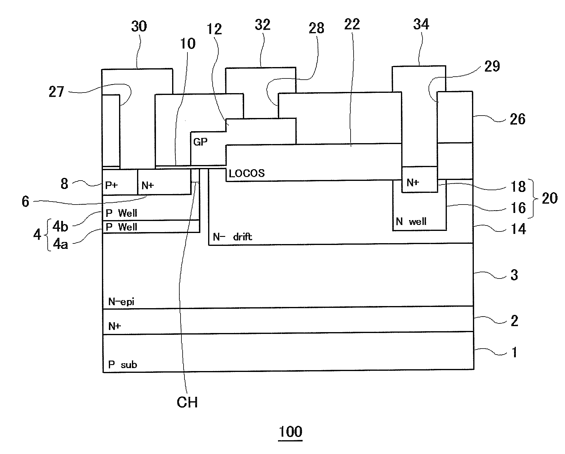
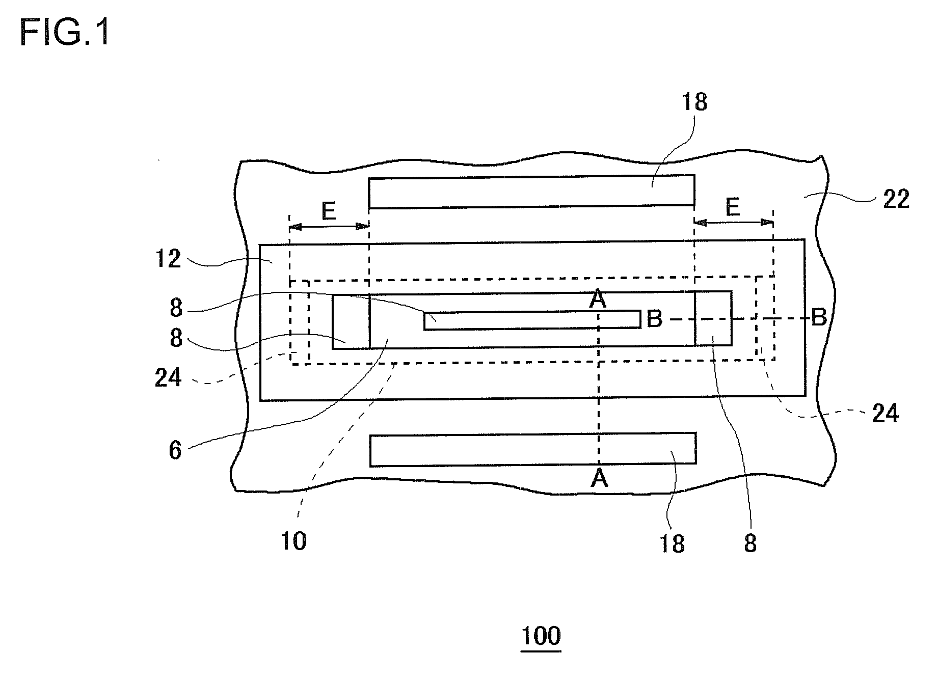
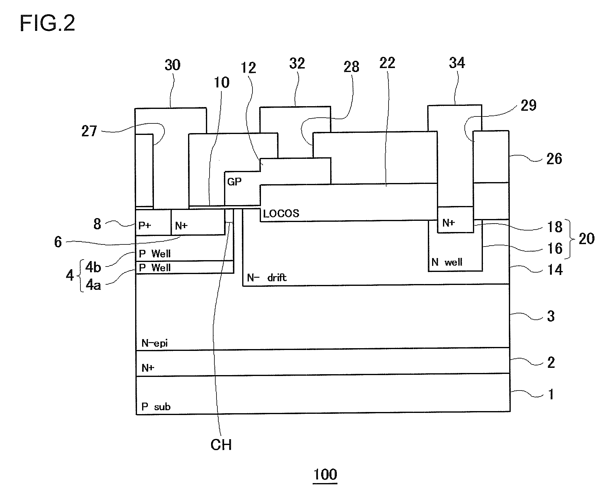
[0043]FIG. 1 is a schematic plan view of a semiconductor device 100 according to a first embodiment of the present invention. FIG. 2 is a cross-sectional view taken along the line A-A of FIG. 1. FIG. 3 is a cross-sectional view taken along the line B-B of FIG. 1. The first embodiment will be described using an N-channel type LDMOS transistor as an example of the semiconductor device 100. Note that in FIG. 1, interlayer insulation films, electrodes, and the like are omitted for ease of explanation.
[0044]As illustrated in FIGS. 1 to 3, the semiconductor device 100 includes a P-type, single-crystal silicon substrate 1, an N+-buried semiconductor layer 2 formed on the silicon substrate 1, and an N−-epitaxial layer 3 (semiconductor layer) formed on the buried semiconductor layer 2. In the first embodiment, only one epitaxial layer 3 is used, but a plurality of epitaxial layers may be stacked. Formed in a surface of the epitaxial layer 3 is a P-type body layer 4 in which a P-type impurity...
second embodiment
[0072]In a second embodiment of the present invention, the region where the thick film portion 24 is disposed differs from that of the first embodiment in which the thick film portion 24 is located in a region closer to the extreme end than the diffusion layer 8 in the end E in the gate-width direction of the gate insulator 10. The same structural components as those of the first embodiment are given the identical reference numerals and the description thereof is omitted as appropriate.
[0073]FIG. 14 is a schematic plan view of a semiconductor device 100 according to the second embodiment.
[0074]In the second embodiment, as shown in FIG. 14, the thick film portion 24 is located at a region of the gate insulator 10 located above the corners on the boundary surface of the body layer 4 which is in contact with the undersurface of the gate insulator 10 in the end E in the gate-width direction.
[0075]In this semiconductor device 100, the concentration of an impurity in the drift layer 14, f...
third embodiment
[0076]In a third embodiment of the present invention, the semiconductor device 100 has the thick film portion 24 disposed in a different region from that of the first and second embodiments. The same structural components as those of the first embodiment are given the identical reference numerals and the description thereof is omitted as appropriate.
[0077]FIGS. 15A and 15B are schematic plan views of semiconductor devices 100 according to the third embodiment.
[0078]In the third embodiment, as shown in FIG. 15A, an approximately U-shaped thick film portion 24 is located in a region in contact with the field insulating film 22 in accordance with the boundary surface of the body layer 4 in the end E in the gate-width direction. That is, the thick film portion 24 is formed in an approximately U shape surrounding the diffusion layer 8.
[0079]Thus, the approximately U-shaped thick film portion 24 provided in the end E in the gate-width direction of the gate insulator 10 serves to alleviate...
PUM
 Abstract
Description
Claims
Application Information
 - R&D
- Intellectual Property
- Life Sciences
- Materials
- Tech Scout
- Unparalleled Data Quality
- Higher Quality Content
- 60% Fewer Hallucinations
Browse by: Latest US Patents, China's latest patents, Technical Efficacy Thesaurus, Application Domain, Technology Topic, Popular Technical Reports.
© 2025 PatSnap. All rights reserved.Legal|Privacy policy|Modern Slavery Act Transparency Statement|Sitemap|About US| Contact US: help@patsnap.com


