

Multiple output magnetic induction unit and a multiple output micro power converter having the same
a technology of multi-output magnetic induction unit and multi-output micro power converter, which is applied in the direction of electric variable regulation, process and machine control, instruments, etc., can solve the problems of reducing the conversion efficiency of dc-dc converter, reducing the mounting area of the power supply module, and reducing the packaging area and cost. , to achieve the effect of low cos
- Summary
- Abstract
- Description
- Claims
- Application Information
AI Technical Summary
Benefits of technology
Problems solved by technology
Method used
Image

Examples
first embodiment
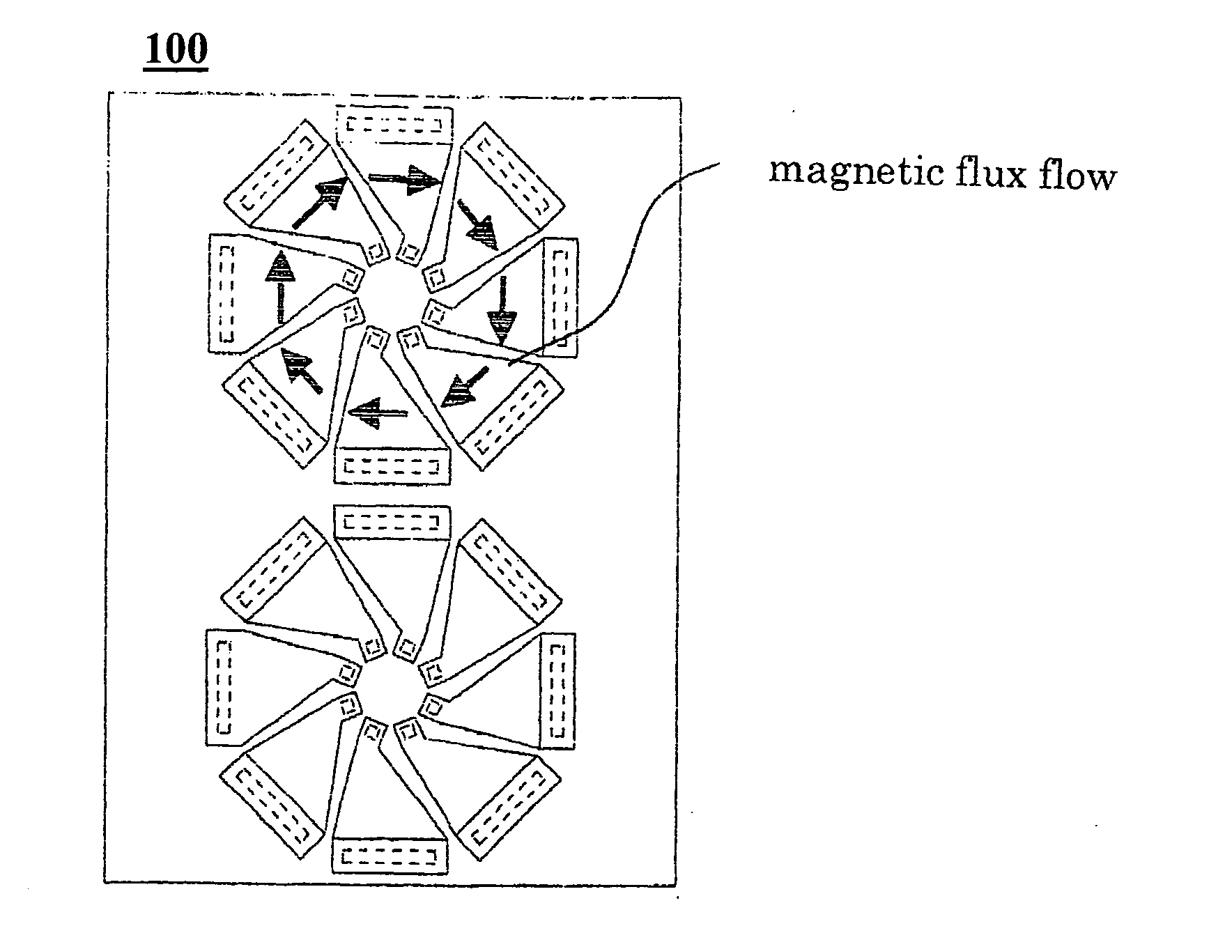
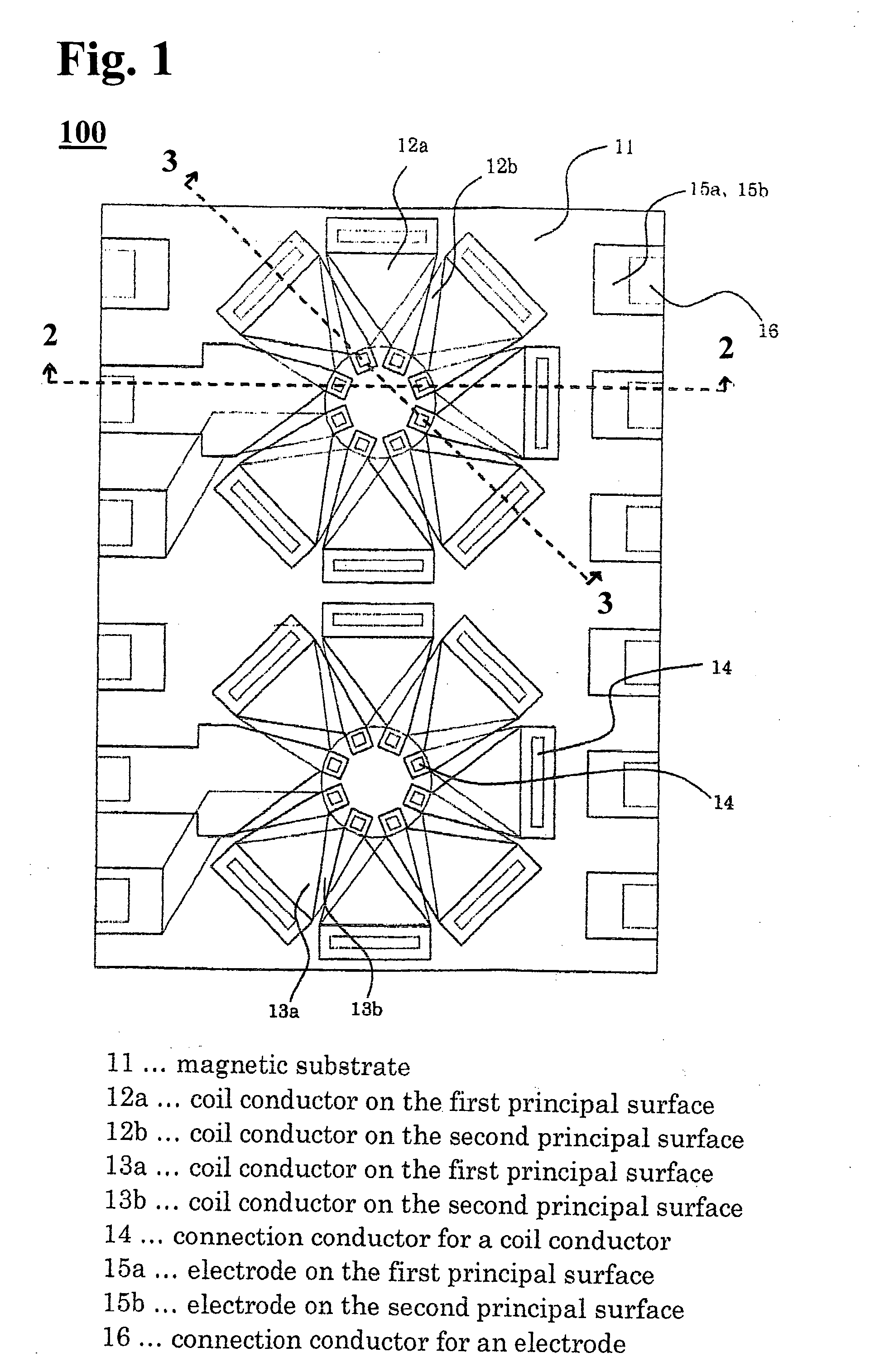
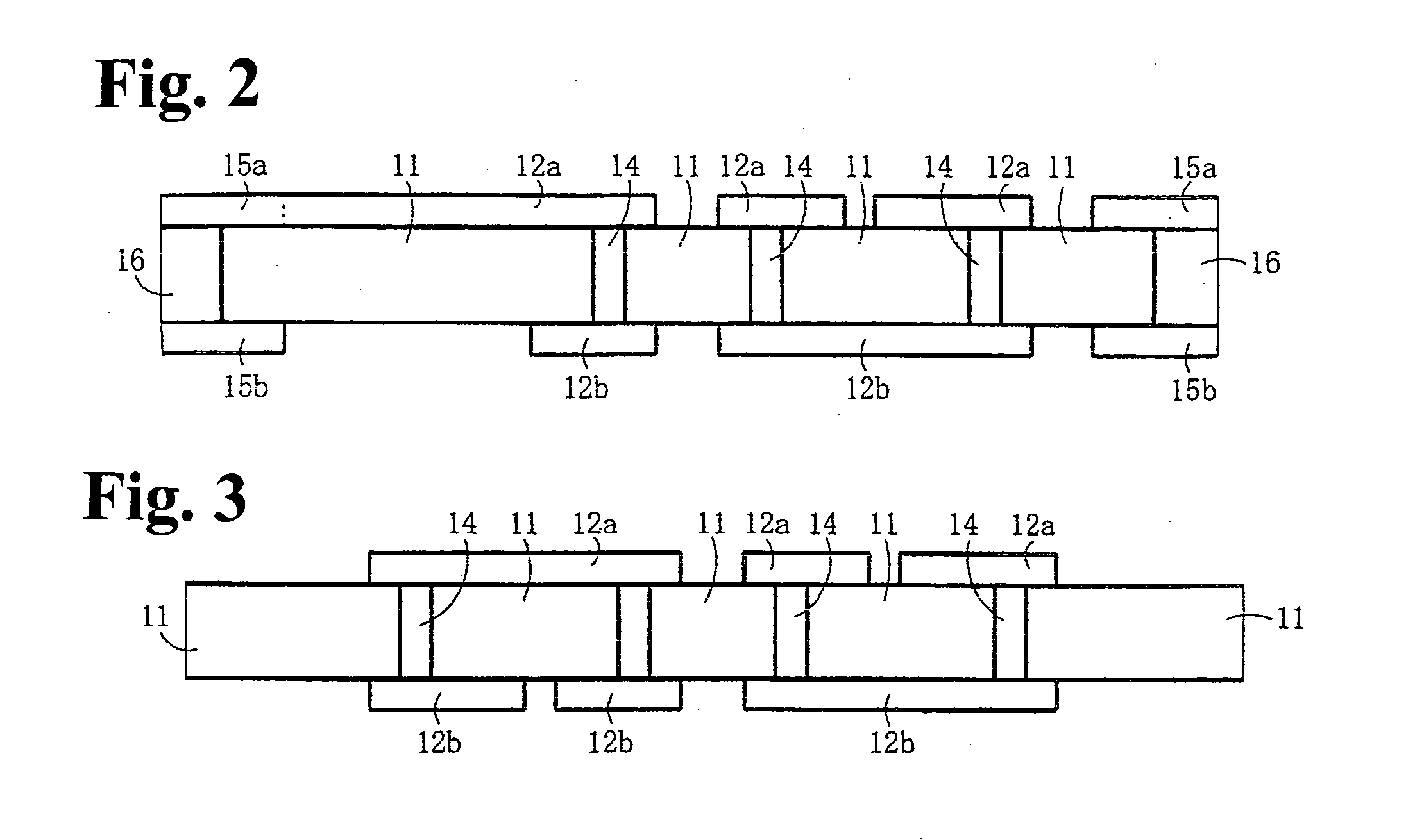
[0039]FIGS. 1 through 3 shows a structure of a multiple output magnetic induction unit according to the first embodiment of the invention, in which FIG. 1 is a top plan view of an essential part, FIG. 2 is a sectional view of the essential part taken along line 2-2 in FIG. 1, and FIG. 3 is sectional view of the essential part taken along line 3-3 in FIG. 1. The multiple output magnetic induction unit 100 depicted in FIGS. 1 through 3 has two inductors of toroidal coils formed on a magnetic substrate 11. FIGS. 1 through 3 illustrate coil configurations of the inductor (coil conductors 12a, 12b, 13a, 13b in a configuration of a toroidal coil) and further, electrodes 15a, 15b for electrical connection.
[0040]The coil conductors 12a, 12b, 13a, 13b are formed using a magnetic substrate 11 for example, a ferrite substrate. The coil conductors 12a, 13a on the first principal surface are electrically connected to the coil conductors 12b, 13b on the second principal surface through connection...
second embodiment
[0058]FIG. 12 is a sectional view of an essential part of a multiple output micro power converter according to the second embodiment of the invention. The multiple output micro power converter 200 includes the multiple output magnetic induction unit 100 shown in FIGS. 1 through 3. A planar packaging technique is used for connection between the multiple output magnetic induction unit 100 and the power supply IC 52.
[0059]The power supply IC 52 is connected to the electrodes 15a formed on the magnetic substrate 11 as shown in FIG. 12. In this embodiment, stud bumps 51 are formed on electrodes (not shown) of the power supply IC, and the power supply IC 52 is fixed on the electrodes 15a by ultrasonic bonding. Then, the power supply IC 52 is fixed to the multiple output magnetic induction unit 100 with the under-filling 53.
[0060]In this embodiment, the power supply IC is fixed to the magnetic induction unit using the stud bumps 51 and ultrasonic bonding. A method of fixing is not limited ...
third embodiment
[0063]FIG. 13 is a sectional view of an essential part of a multiple output micro power converter according to the third embodiment of the invention. The multiple output micro power converter 300 comprises the multiple output magnetic induction unit 100 shown in FIGS. 1 through 3 and utilizes the wire-bonding technique to connect the multiple output magnetic induction unit 100 and the power supply IC.
[0064]The power supply IC 52 with a die attachment film 62 pasted on the back surface thereof is mounted on the magnetic substrate 11, and electrodes (not shown) on the power supply IC 52 are connected to the electrodes 15a on the magnetic substrate 11 by wire bonding with gold wires 61. After the wire bonding, a sealing process is carried out with a sealant of epoxy resin 63, for example. While an adhesive of a die attachment film 62 is used for mounting the power supply IC 52 in the embodiment, a liquid adhesive may be used.
[0065]While gold wires 61 are used, aluminum wires can altern...
PUM
 Abstract
Description
Claims
Application Information