Electric Machine Assembly

a technology of electric machines and assembly parts, which is applied in the direction of synchronous machines with stationary armatures, magnetic circuits characterised by magnetic materials, magnetic circuits, etc., can solve the problems of reducing machine performance and efficiency, and achieve the effect of increasing performan

Inactive Publication Date: 2009-10-01
HOGANAS AB
View PDF17 Cites 42 Cited by
  • Summary
  • Abstract
  • Description
  • Claims
  • Application Information

AI Technical Summary

Benefits of technology

[0004]It is, therefore, an object of the present invention ...

Problems solved by technology

However, one of the drawbacks of the design is that they are typically relatively expensive to manufactu...

Method used


Image

  • Electric Machine Assembly
  • Electric Machine Assembly
  • Electric Machine Assembly

Examples


Embodiment Construction

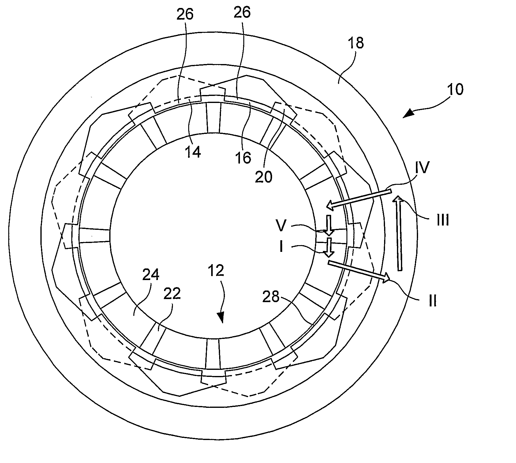
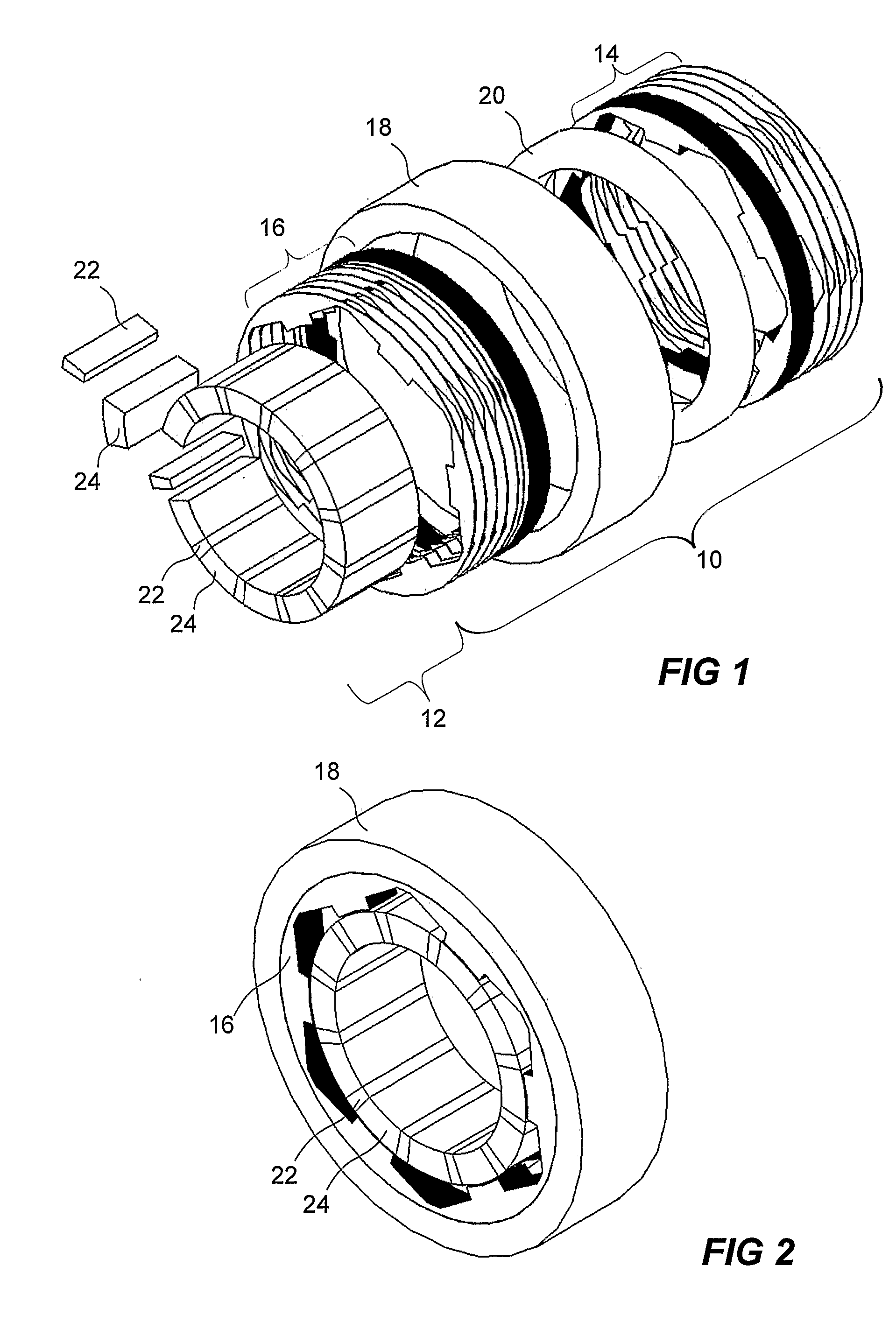
[0033]FIGS. 1-3 shows one embodiment of the rotary machine according to the invention. This embodiment comprises a stator assembly 10 and a rotor 12.

[0034]The stator assembly includes a first stator core section 14, a second stator core section 16, a stator yoke section 18 and a coil 20.

[0035]The rotor includes permanent magnets 22 and pole sections 24.

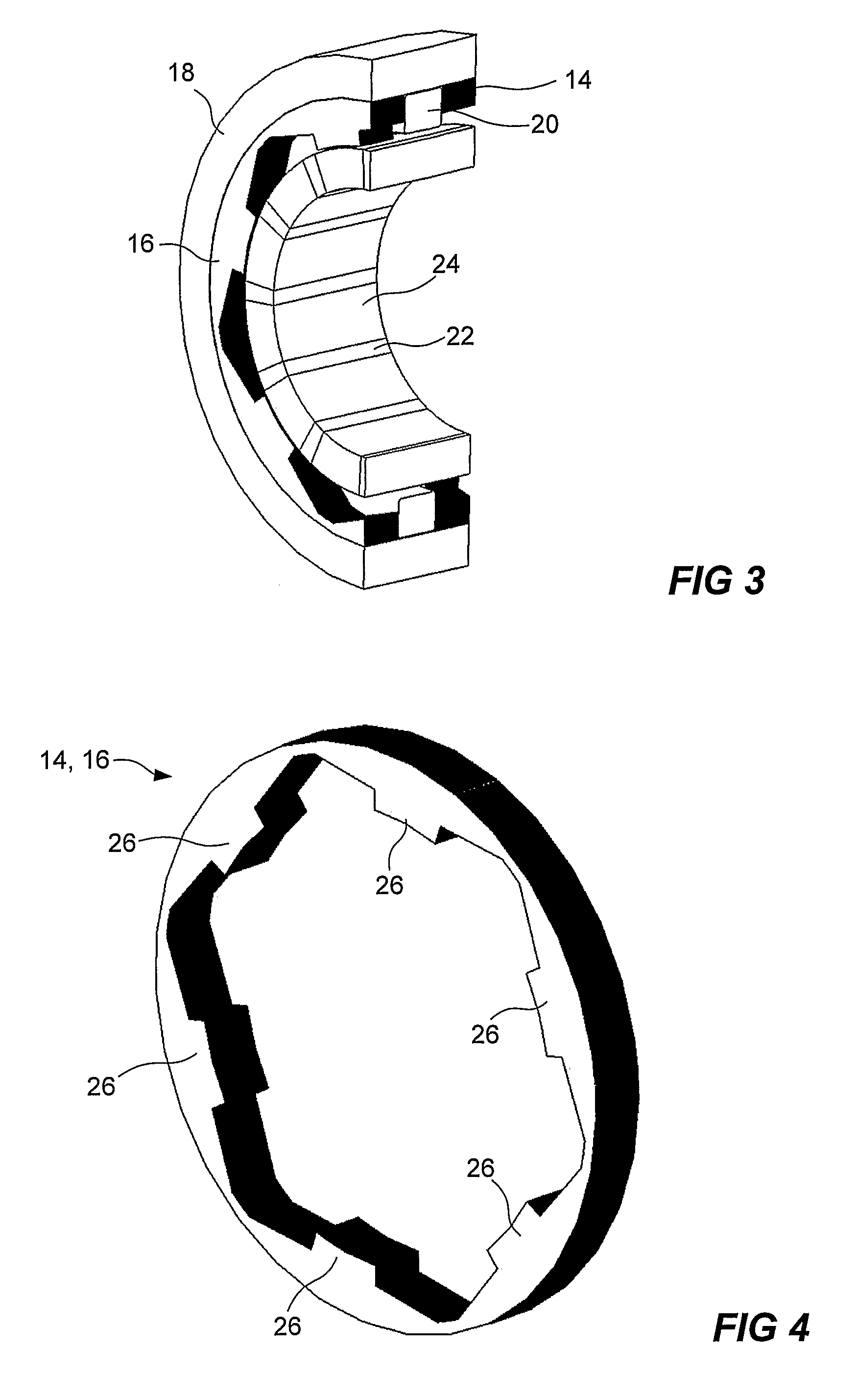
[0036]The stator yoke section 18 of the stator is arranged to provide a magnetic flux path between the first and second stator core sections 14,16, thereby acting as a “flux bridge”. The material used for the stator yoke section 18 may be soft magnetic powder in order to facilitate the assembly of the stator and to provide a relatively low reluctance transition between the two stator core sections 14, 16.

[0037]In FIG. 4 an embodiment of the stator core sections 14, 16 used in the embodiment of FIGS. 1-3 is shown. The figure only shows one stator core section. However, according to one embodiment the two stator core sections 14, 16 are...


PUM


Abstract

An electrical rotary machine is provided comprising a first stator core section being substantially circular and including a plurality of teeth, a second stator core section being substantially circular and including a plurality of teeth, a coil arranged between the first and second circular stator core sections, and a rotor including a plurality of permanent magnets. The first stator core section, the second stator core section, the coil and the rotor are encircling a common geometric axis, and the plurality of teeth of the first stator core section and the second stator core section are arranged to protrude towards the rotor. Additionally, the teeth of the second stator core section are circumferentially displaced in relation to the teeth of the first stator core section, and the permanent magnets in the rotor are separated in the circumferential direction from each other by axially extending pole sections made from soft magnetic material.

Description

TECHNICAL FIELD OF THE INVENTION[0001]The present invention generally relates to a rotary machine. More particularly this invention relates to an electrical, rotary machine, comprising a first stator core section including a plurality of teeth and being substantially circular, a second stator core section including a plurality of teeth and being substantially circular, a coil arranged between the first and second circular stator core sections, and a rotor including a plurality of permanent magnets. Further, the first stator core section, the second stator core section, the coil and the rotor are encircling a common geometric axis, and the plurality of teeth of the first stator core section and the second stator core section are arranged to protrude towards the rotor.BACKGROUND OF THE INVENTION[0002]In later years electric machine designs evolved from modulated pole machines, claw pole machines, Lundell machines and transverse flux machines (TFM), have become more and more interestin...

Claims


Application Information

Patent Timeline
IPC IPC(8): H02K1/12H02K15/12H02K1/276
CPCH02K1/145H02K1/148H02K1/146H02K21/145H02K1/02H02K1/2773
Inventor JACK, ALANPINGUEY, EDWINNORD, GORAN
Owner HOGANAS AB
Why Eureka
Try Eureka