
Mixer and frequency converting apparatus

Active Publication Date: 2009-10-01
TDK CORPARATION
View PDF3 Cites 14 Cited by
  • Summary
  • Abstract
  • Description
  • Claims
  • Application Information

AI Technical Summary

Benefits of technology

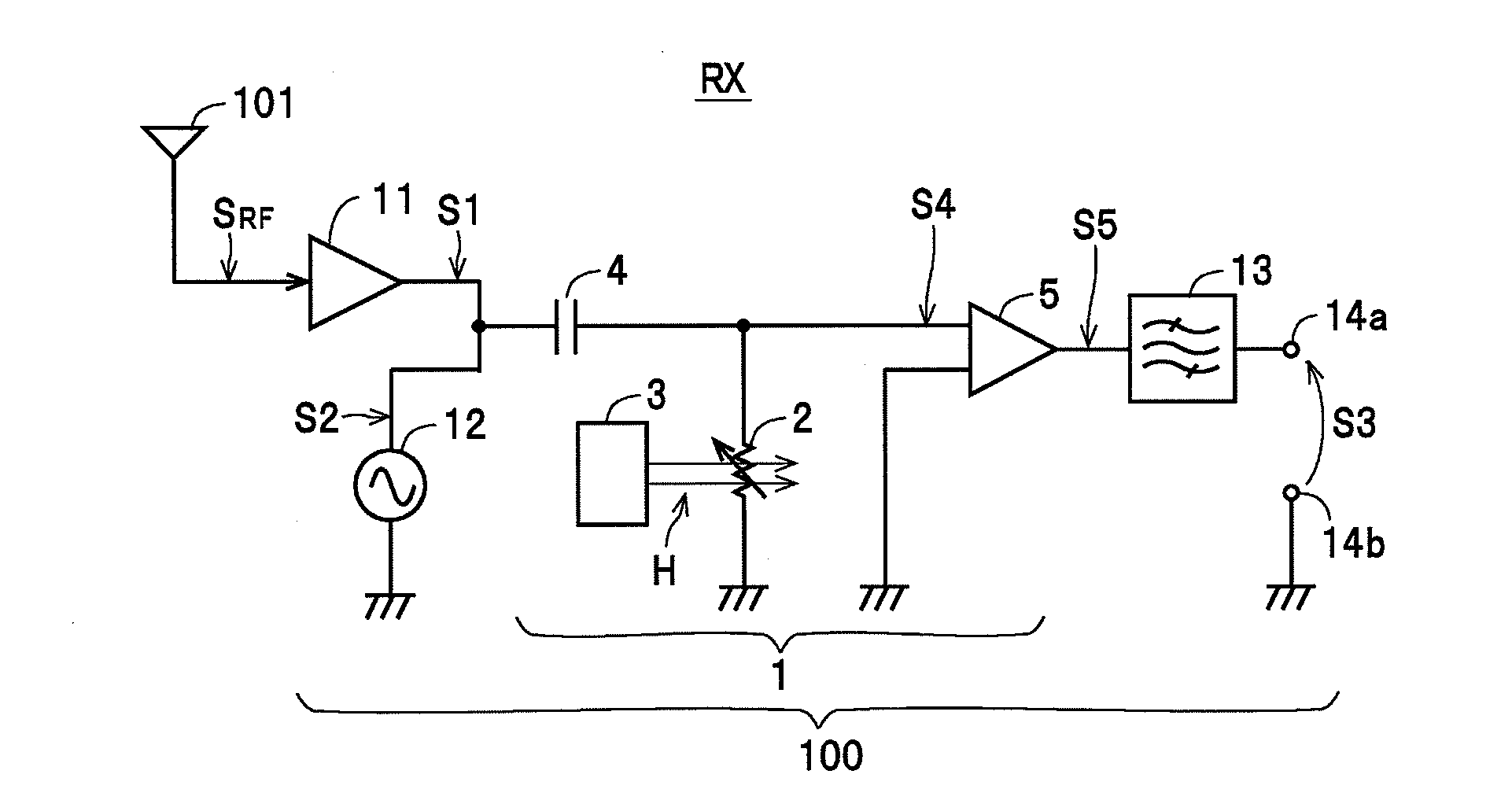
[0009]According to the above mixer, by including the magnetoresistive effect element and the magnetic field applying unit that applies a magnetic field to the free magnetic layer and multiplying a first high-frequency signal and a second high-frequency signal as a local signal when inputted using the magnetoresistive effect element to generate a multiplication signal, the first high-frequency signal and the second high-frequency signal are mixed (multiplied) using a square-law detection function (spin torque diode effect) realized when the magnetoresistive effect element resonates. By doing so, it is possible to mix (multiply) the first high-frequency signal and the second high-frequency signal and generate a multiplication signal using the second high-frequency signal (a local signal) of low power compared to a construction that uses a semiconductor pn junction diode. Therefore, according to the mixer and a frequency converting apparatus, it is possible to reduce power consumption by an amount corresponding to the reduction in the power of the second high-frequency signal.
[0013]According to the above mixer, since the construction of the magnetic field applying unit can be simplified, it is possible to reduce the manufacturing cost.
[0015]According to the above mixer, when a DC voltage is generated in the magnetoresistive effect element, it is possible for the capacitance element to prevent the DC voltage from leaking and to protect the magnetoresistive effect element and the like.
[0017]According to the above mixer, by using a simple construction, it is possible to provide the mixer with an amplification function while reducing the manufacturing cost.
[0021]According to the above frequency converting apparatus, since it is possible to cause strong resonance (spin torque ferromagnetic resonance) of the magnetoresistive effect element, it is possible to reliably cause the magnetoresistive effect element to carry out a square-law detection operation on the high-frequency signals.

Problems solved by technology

However, even though the above phenomenon of TMR elements is known, no magnetic device that can put such phenomenon to industrial use is known, and application of such discovery is awaited.

Method used


Image

  • Mixer and frequency converting apparatus
  • Mixer and frequency converting apparatus
  • Mixer and frequency converting apparatus

Examples


Embodiment Construction

[0031]Preferred embodiments of a mixer and a frequency converting apparatus according to the present invention will now be described with reference to the attached drawings.

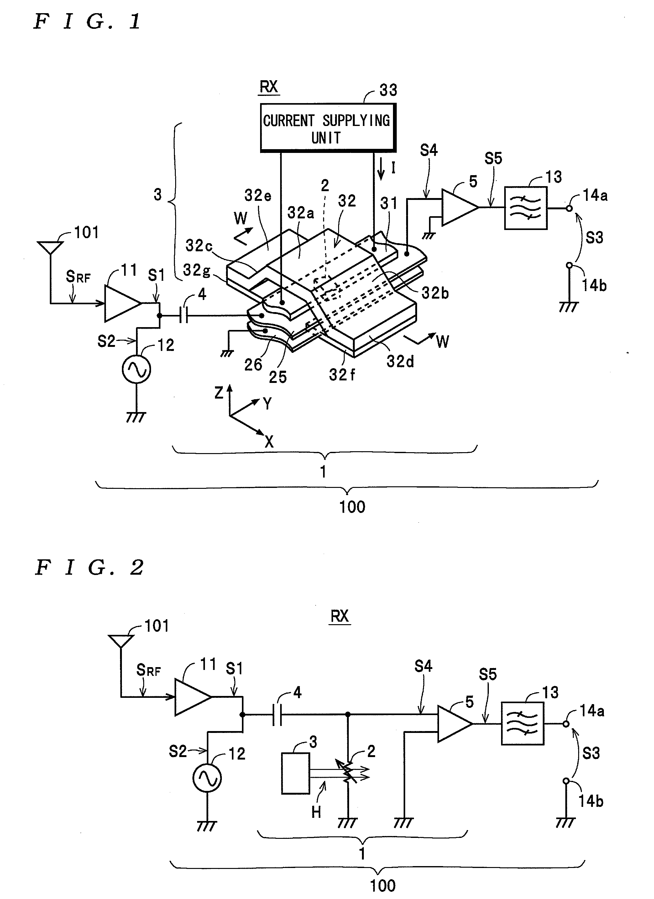
[0032]First, the constructions of a mixer 1 and a frequency converting apparatus 100 that includes the mixer 1 will be described with reference to the drawings. Note that an example where the frequency converting apparatus 100 has been applied to a receiver apparatus RX will be described as an example.

[0033]The frequency converting apparatus 100 shown in FIG. 1 constructs the receiver apparatus RX together with an antenna 101. The frequency converting apparatus 100 is disposed at a high-frequency stage of the receiver apparatus RX that receives an RF signal SRF outputted from the antenna 101 and functions so as to convert the frequency of the RF signal SRF to the frequency of a multiplication signal S3. As one example, the frequency converting apparatus 100 includes the mixer 1 and an amplifier 11, a signal gener...


PUM


Abstract

A mixer includes: a magnetoresistive effect element including a fixed magnetic layer, a free magnetic layer, and a nonmagnetic spacer layer disposed between the fixed magnetic layer and the free magnetic layer; and a magnetic field applying unit that applies a magnetic field to the free magnetic layer. The mixer is operable, when a first high-frequency signal and a second high-frequency signal as a local signal are inputted, to multiply the first high-frequency signal and the second high-frequency signal using the magnetoresistive effect element and to generate a multiplication signal. A frequency converting apparatus includes the mixer and a filter operable, when a higher frequency and a lower frequency out of frequencies of the first high-frequency signal and the second high-frequency signal are expressed as f1 and f2 respectively, to pass one out of a frequency (f1+f2) and a frequency (f1-f2) out of the multiplication signal.

Description

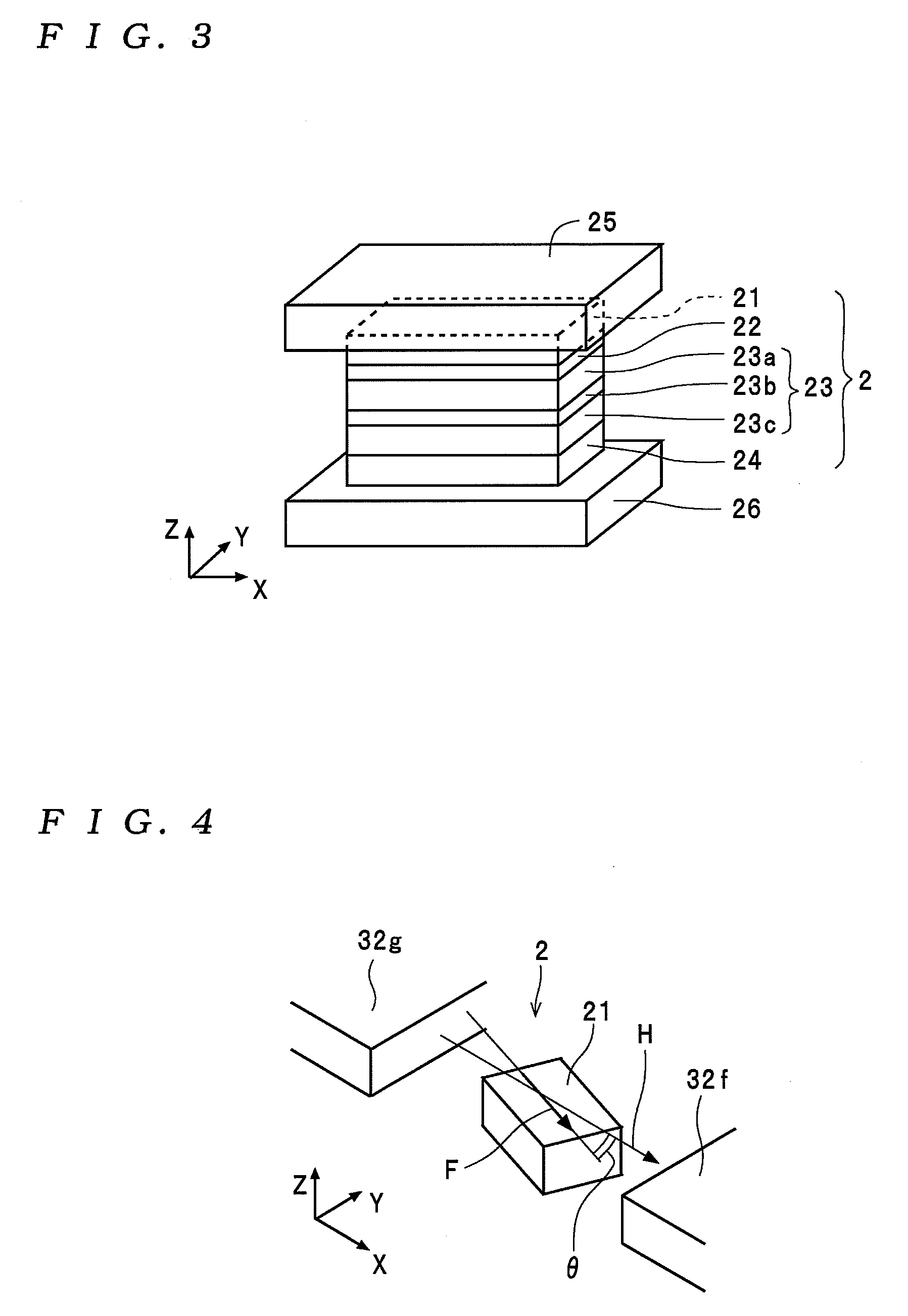
BACKGROUND OF THE INVENTION[0001]1. Field of the Invention[0002]The present invention relates to a mixer that generates a multiplication signal using a magnetoresistive effect element and a frequency converting apparatus equipped with such mixer.[0003]2. Description of the Related Art[0004]A TMR (Tunnel MagnetoResistive) element constructed with a spacer layer formed of a nonmagnetic material between a fixed magnetic layer and a free magnetic layer is known as one example of a magnetoresistive effect element. In a TMR element, spin-polarized electrons flow when a current passes, and the magnetic orientation of the free magnetic layer (i.e., the orientation of an electronic spin) changes in accordance with the number of spin-polarized electrons that accumulate inside the free magnetic layer. When an attempt is made to change the magnetic orientation of a free magnetic layer that has been disposed in a certain magnetic field, torque will act so as to restore the electron spin to a sta...

Claims


Application Information

Patent Timeline
IPC IPC(8): G06G7/16
CPCH03D7/00
Inventor KAKINUMA, YUJIKOGA, KEIJI
Owner TDK CORPARATION
Learn More