Imaging filter

a filter and image technology, applied in the field of image filters, can solve the problems of noise or false signals, difficult to prevent the formation of clearances, and more difficult processing of through holes, so as to achieve excellent mass production adequacy and reduce manufacturing costs

Inactive Publication Date: 2009-10-01
FUJI PHOTO OPTICAL CO LTD
View PDF17 Cites 20 Cited by
  • Summary
  • Abstract
  • Description
  • Claims
  • Application Information

AI Technical Summary

Benefits of technology

[0013]In consideration of the above, an object of the invention is to provide an imaging filter in which a mass production adequacy is excellent, a manuf

Problems solved by technology

In the contact type image scanner, it is impossible to prevent a clearance from being formed between an imaging target and an image sensor.
For this reason, light emitted from a single point of the imaging target is obliquely incident on both of adjacent photodiodes, resulting in a noise or a false signal.
If a diameter of the through hole is decreased and an interval between the through holes is reduced, it is more difficult to carry out a processing for forming the through hole.
Even if a very small through hole can be provided by a mechanical processing, the cost is increased for the imaging filter.
However, it is hard to carry out a special processing over the internal

Method used


Image

  • Imaging filter
  • Imaging filter
  • Imaging filter

Examples


first embodiment

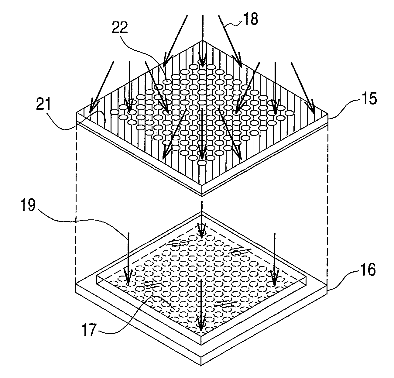
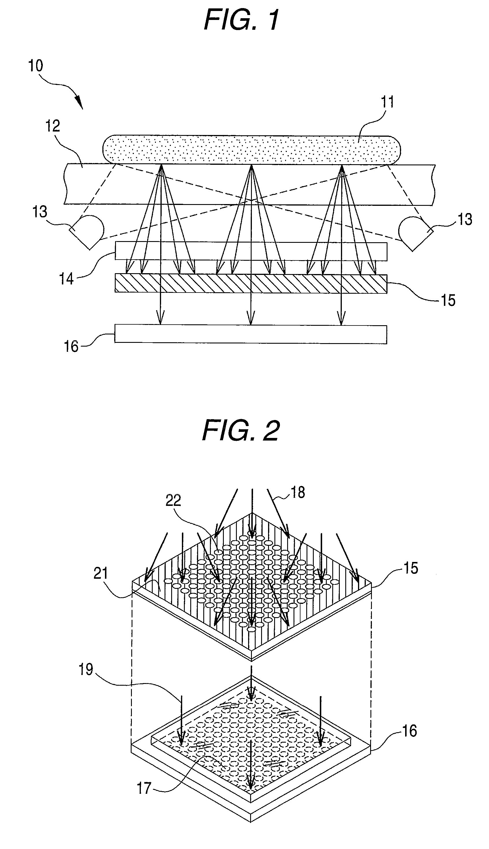
[0057]As shown in FIG. 1, a contact type scanner 10 is an imaging apparatus for taking an image of an object 11 which is caused to come in almost close contact with an image sensor 16 and includes a protecting cover 12, an LED 13, a band-pass filter 14, an angle limiting filter 15 and the image sensor 16. The protecting cover 12 is a transparent glass plate and protects the angle limiting filter 15 and the image sensor 16 which are disposed thereunder from flaw or dust. The object 11 which is to be subjected to imaging is directly mounted on the protecting cover 12.

[0058]The LED 13 emits an infrared ray having a wavelength of 850 nm and uniformly illuminates the object 11 mounted on the protecting cover 12. The infrared ray emitted from the LED 13 is scattered to reflect an absorptance and a reflectance of the infrared ray which are varied depending on a place of the object 11, and a part thereof is incident in a direction of the angle limiting filter 15 provided under the protectin...

second embodiment

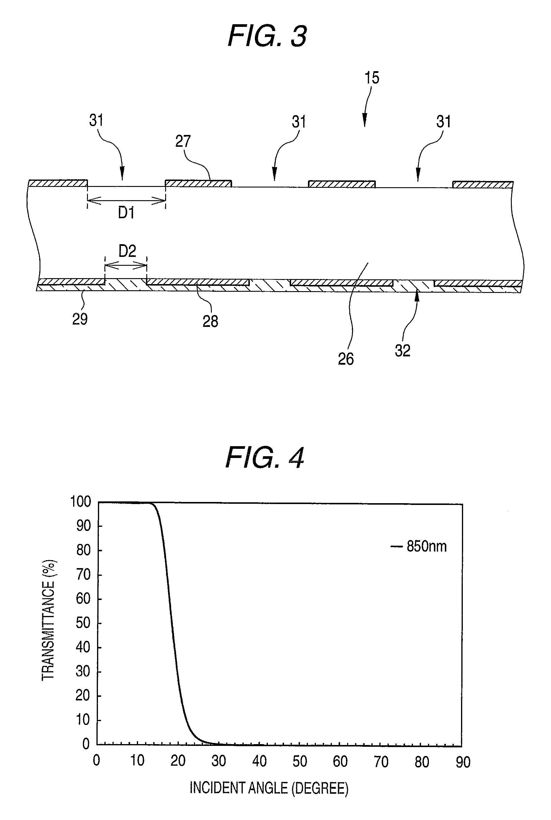
[0079]Although the first shielding film 27 and the second shielding film 28 are provided in the outside and the inside of the glass substrate 26 in the first embodiment, the invention is not limited to this configuration but the shielding film may be provided on only one surface of the glass substrate 26. An example where the shielding film is provided on one surface of the glass substrate 26 will be described now as a second embodiment of the invention. For example, in an angle limiting filter 41 shown in FIG. 9, a shielding film 42 is provided on the surface of the glass substrate 26 facing the object 11 and no shielding film is provided on only the surface facing the image sensor 16, unlike the above-mentioned angle limiting filters 15 and 35. The incident angle-dependent reflecting film 29 is provided on the surface of the glass substrate 26 facing the object 11 so as to cover the entire shielding film 42.

[0080]The shielding film 42 provided in the angle limited filter 41 is obt...


PUM


Abstract

An imaging filter disposed on a front surface of an image sensor and serving to limit an incident angle of light on the image sensor is provided. The filter includes: a transparent substrate; a first shielding film provided on the front surface of the substrate and having a plurality of incidence openings, the incidence openings having a constant size and provided at an interval; a second shielding film provided on a back surface of the substrate and having a plurality of emission openings, the emission openings having a constant size and having centers which are coincident with the incidence openings; and a reflecting film provided on at least one of the front surface and the back surface of the substrate and including a multilayer dielectric film that transmits light having a wavelength and being incident almost vertically on the reflecting film and that that reflects the light having the wavelength and being incident obliquely on the reflecting film.

Description

[0001]This application is based on and claims priority under 35 U.S.C. § 119 from Japanese Patent Application No. 2008-073705, filed on Mar. 21, 2008, the entire disclosure of which is herein incorporated by reference.BACKGROUND OF THE INVENTION[0002]1. Field of the Invention[0003]The present invention relates to an imaging filter to be used in a contact type imaging apparatus for causing an image sensor to come in close contact with an object, thereby carrying out imaging, and more particularly to an imaging filter for limiting an incident angle of light on the image sensor of the imaging apparatus.[0004]2. Description of Related Art[0005]An image scanner for taking an image of an original such as a picture or a document to obtain digital image data has spread. For the image scanner, there has been known a contact type image scanner which causes a line image sensor having an equal width to an original to be read to come in almost contact with the original, thereby carrying out imag...

Claims


Application Information

Patent Timeline
IPC IPC(8): G02B5/26
CPCG02B5/26H04N1/024H04N1/028
Inventor YOKOYAMA, IWAOHIROSE, NORIYOSHIKURAHASHI, HAJIME
Owner FUJI PHOTO OPTICAL CO LTD
Why Eureka
Try Eureka