Substrate cleaning method and substrate cleaning apparatus

a cleaning method and substrate technology, applied in the direction of cleaning processes, cleaning methods, instruments, etc., can solve the problems of remaining dissolved products, dissolved products cannot be fully eliminated by spin cleaning methods, and dissolved products may appear as development faults, etc., to achieve high cleaning effect and perform cleaning processes.

Active Publication Date: 2009-10-08
TOKYO ELECTRON LTD
View PDF4 Cites 45 Cited by
  • Summary
  • Abstract
  • Description
  • Claims
  • Application Information

AI Technical Summary

Benefits of technology

[0014]The present invention has been made in view of the above circumstances. The object of the present invention is to provide a technique for producing a high cleaning effect and performing a cleaning process for a short period, even for a water-repellent material whose static contact angle with respect to water on a surface thereof is 85 degrees or more.

Problems solved by technology

However, there is a possibility that the dissolved matters (dissolved products) cannot be fully eliminated by the spin cleaning method.
However, when a line width thereof is narrow, it is highly possible that some remaining dissolved products may appear (remain) as development faults.
However, even when the spin-cleaning process is performed for such a long time, some dissolved products may be left, i.e., a desired perfect cleaning may not be performed.
One of problems of this immersion exposure process is that there is a possibility that a wafer on which water droplets remain may be transferred from an exposure apparatus to an application and development apparatus.
In this case, presence of the water droplets on the wafer, or presence of so-called water marks, which are water stains generated by the dried water droplets, may adversely affect the resolution of a pattern directly below the water droplets or the water marks.
However, it is all the more likely that small water droplets remain on a surface of the protective film because of the high water repellency of the protective film.
In a scanning process by the immersion part, when particles remain on the surface of the substrate, the particles may be taken into a liquid existing under the immersion part, resulting in development faults.
That is, development faults may be caused by the particles in respective scanning positions.
However, in the method of the Patent Document 1, since a contact angle of the surface with respect to the wafer is large, i.e., the surface has a high water repellency, it is difficult to fully remove the particles (before the immersion exposure process) or water droplets (after the immersion exposure process) in an area remote from a central part of the wafer.
Since this cleaning liquid R contains dissolved products of the resist, the cleaning liquid R causes a development fault.
However, the Patent Document 2 does not describe a technique for reliably cleaning the overall surface of the wafer, i.e., from an area near to the central part of the wafer to a periphery thereof, when the surface of the wafer has a contact angle of as large as 85 degrees or more.
Specifically, there may arise problems in that the dried area may not be suitably formed depending on sizes of the cleaning-liquid nozzle and the gas nozzle and / or in that the nozzle-movement speed is so slow that the process period is long.

Method used


Image

  • Substrate cleaning method and substrate cleaning apparatus
  • Substrate cleaning method and substrate cleaning apparatus
  • Substrate cleaning method and substrate cleaning apparatus

Examples


first embodiment

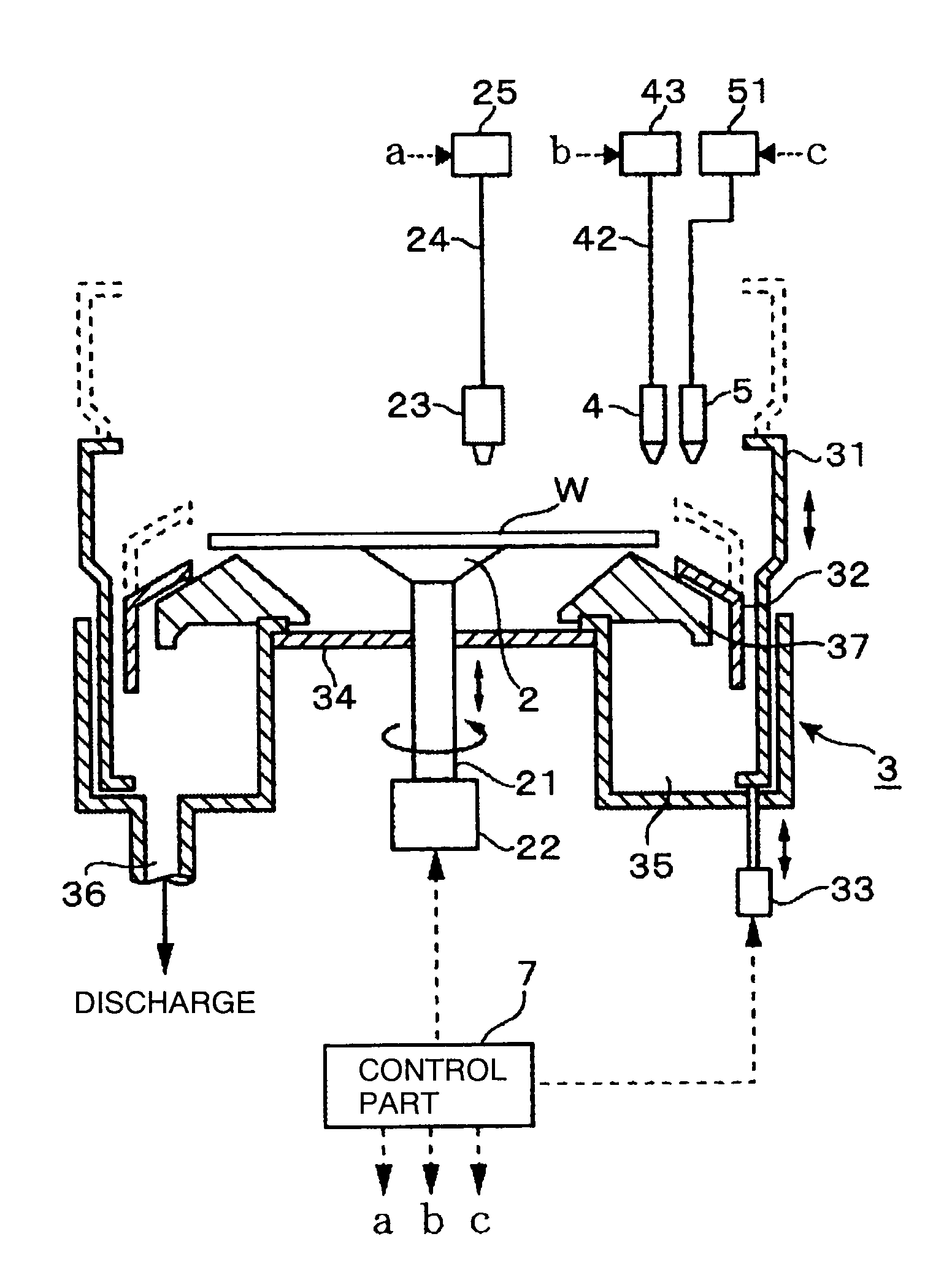
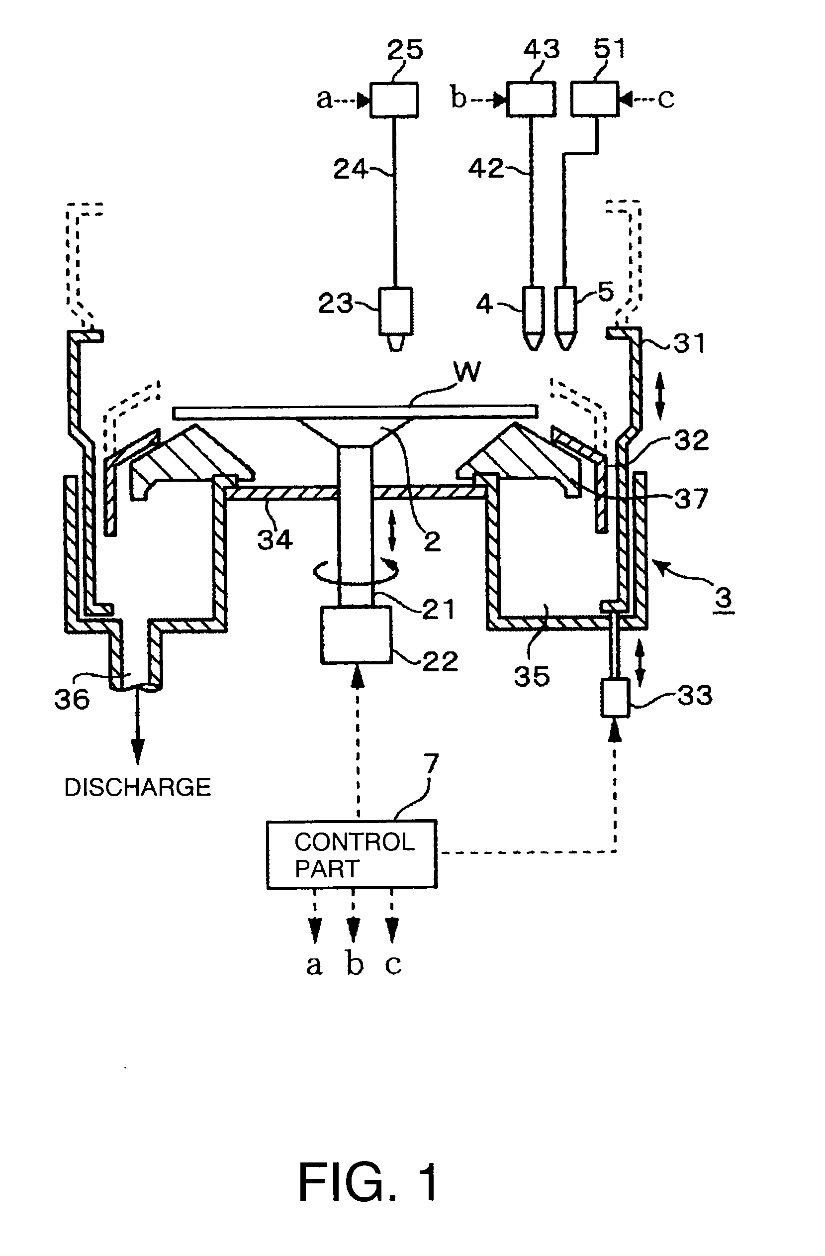
[0060]A first embodiment of a substrate cleaning apparatus according to the present invention is described. The apparatus is combined with (integrated with) a development apparatus. In FIG. 1, the reference number 2 depicts a spin chuck which is a substrate holder that sucks and absorbs a central part of a rear surface of a substrate such as a wafer W, so as to hold the wafer W in a horizontal posture. The spin chuck 2 is connected via a rotation shaft 21 to a drive mechanism 22 including a rotation mechanism, and is configured to be capable of being rotated and moved in a vertical direction, with the wafer W being held by the spin chuck 2. In this example, a center of the wafer W is designed to be positioned on the rotation shaft 21 of the spin chuck 2.

[0061]A cup member 3 having an upper opening is disposed to surround the wafer W placed on the spin chuck 2. The cup member 3 is composed of an outer cup 31 whose upper part is a rectangular hollow pillar and whose lower part is cyli...

second embodiment

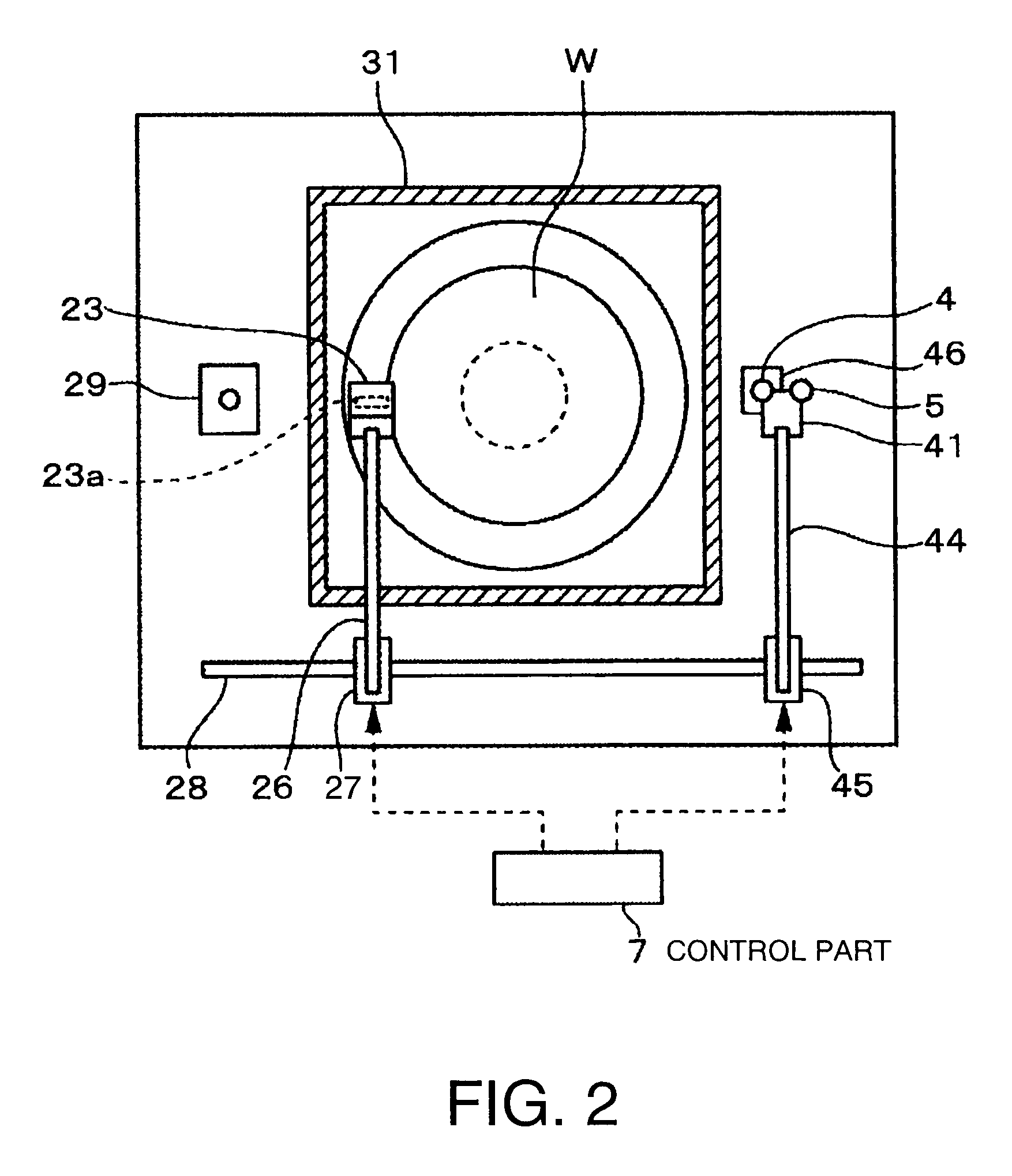
[0086]In this embodiment, a cleaning-liquid nozzle 4 and a gas nozzle 5 can be independently moved by separate nozzle arms. At first, a cleaning liquid is discharged from the cleaning-liquid nozzle 4 to a central part C of a wafer W. Subsequently, the cleaning-liquid nozzle 4 is slightly moved outward from the central part C of the wafer W, and the gas nozzle 5 is positioned to be opposed to the central part C of the wafer W. Then, an N2 gas is supplied from the gas nozzle 5 to the central part C so as to form a dried area 6. Thereafter, the cleaning-liquid nozzle 4 is moved in a vicinity of a peripheral part of the wafer W, with the cleaning liquid R being discharged (FIGS. 10A and 10B). Then, the discharge of the cleaning liquid R is stopped, and the wafer W is dried (FIG. 10C). On the other hand, after the N2 gas G has been supplied from the gas nozzle 5 to the central part C so as to form the dried area 6, the gas nozzle 5 stops the discharge of the N2 gas G.

[0087]A separation d...

third embodiment

[0089]Since a developer and a cleaning liquid are supplied, an atmosphere inside the cup 31 is high in humidity. In particular, immediately after the cleaning liquid R has been supplied, humidity of the atmosphere surrounding the area onto which the cleaning liquid R has been supplied is raised. Thus, in the step 3 of the first embodiment, when the gas nozzle 5 following the cleaning-liquid nozzle 4 is moved from the central part C of the wafer W toward the peripheral part thereof, there is a possibility that moisture of the surrounding atmosphere might adhere to a surface of the gas nozzle 5 so as to form liquid droplets thereon. In this case, the liquid droplets may fall down from the gas nozzle 5 to the dried area 6 and enter a recess formed in the dried area 6 to thereby cause a development fault. Thus, there is described a third embodiment capable of restraining a development fault which might be caused by the falling liquid droplets.

[0090]FIG. 11 shows a development apparatus ...


PUM


Abstract

The present invention relates to a substrate cleaning method for cleaning a substrate whose static contact angle with respect to water is 85 degrees or more. The substrate cleaning method includes a step in which the substrate is held horizontally by a substrate holder in such a manner that a central part of the substrate and a central part in rotation correspond to each other; a step in which, while the substrate holder is being rotated about a vertical axis, a cleaning liquid is discharged from a cleaning-liquid nozzle to the central part of the substrate and is spread over all the surface of the substrate by a centrifugal force; a step in which, while the substrate holder is being continuously rotated, a to-be-discharged position of the cleaning liquid on the substrate is changed to an eccentric position deviated from the central part of the substrate, and a gas is discharged from a gas nozzle to the central part of the substrate so as to form a dried area of the cleaning liquid under a condition in which a distance between an interface on a side of a to-be-discharged position of the gas in the to-be-discharged position of the cleaning liquid and an interface on a side of the to-be-discharged position of the cleaning liquid in the to-be-discharged position of the gas is set between 9 mm and 15 mm; and a step in which, while the substrate holder is being continuously rotated, the to-be-discharged position of the cleaning liquid is moved toward a periphery of the substrate at a speed lower than a speed at which the dried area is spread outward.

Description

FIELD OF THE INVENTION[0001]The present invention relates to a substrate cleaning method and a substrate cleaning apparatus, for cleaning a substrate whose surface is hydrophobic, such as a substrate onto which a resist used for an immersion exposure process has been applied, and a substrate that has been further developed after an immersion exposure process.BACKGROUND ART[0002]In a photoresist step as one of semiconductor manufacturing steps, a resist is conventionally applied to a surface of a semiconductor wafer (hereinafter referred to as “wafer”) which is a substrate, and the wafer is developed after an exposure process so as to form a resist pattern in the surface. Such a series of processes is generally performed by a system in which an exposure apparatus is connected to an application and development apparatus configured to apply and develop a resist.[0003]In the developing process in the series of processes, a developer is supplied onto a wafer, and then the wafer is kept i...

Claims


Application Information

Patent Timeline
Patent Type & Authority Applications(United States)
IPC IPC(8): B08B7/04
CPCB08B3/024H01L21/67051G03F7/3021G03F7/168H01L21/304
Inventor YOSHIHARA, KOUSUKEYOSHIDA, YUICHIYAMAMOTO, TARO
Owner TOKYO ELECTRON LTD
Why Eureka
Try Eureka