White light emitting diode and lighting apparatus using the same

a technology of white light and led chip, which is applied in the direction of lighting and heating apparatus, semiconductor devices, light sources, etc., can solve the problems of difficult to implement a uniform mixed color, low power consumption and a long lifespan, and reduce luminance efficiency, so as to enhance luminance efficiency and heat radiation characteristics, minimize the re-absorption of fluorescence into led chips, and the effect of high refractive index

Inactive Publication Date: 2009-10-08
SAMSUNG ELECTRONICS CO LTD
View PDF5 Cites 65 Cited by
  • Summary
  • Abstract
  • Description
  • Claims
  • Application Information

AI Technical Summary

Benefits of technology

[0013]An advantage of the present invention is that it provides a white LED in which a fluorescence reflecting layer having a lower refractive index than a phosphor layer is provided between an LED chip and the phosphor layer so as to totally reflect some of fluorescence emitted from the phosphor layer in the upward direction, thereby minimizing the re-absorption of the fluorescence into the LED chip. Therefore, it is possible to enhance luminance efficiency and heat radiation characteristics.
[0014]Another advantage of the invention is that it provides a white LED lighting apparatus using the white LED.
[0015]Additional aspects and advantages of the present general inventive concept will be set forth in part in the description which follows and, in part, will be obvious from the description, or may be learned by practice of the general inventive concept.
[0016]According to an aspect of the invention, a white LED comprises a substrate having a reflecting body provided thereon; an LED chip mounted on the substrate; a fluorescence reflecting layer formed on the LED chip; and a phosphor layer formed on the fluorescence reflecting layer and having a higher refractive index than the fluorescence reflecting layer.
[0017]The LED chip may include at least one or more LEDs which generate blue, red, green, and ultraviolet (UV) wavelengths. Preferably, the LED chip includes a blue LED
[0018]The phosphor layer may be formed of phosphor which converts a wavelength into any one of yellow, red, and green wavelengths. Preferably, the phosphor layer is formed of yellow light emitting phosphor.

Problems solved by technology

The LED has low power consumption and a long lifespan.
In particular, color spots may occur, which makes it difficult to implement a uniform mixed color.
Therefore, luminance efficiency decreases, and a large amount of heat is generated from the LED chip.

Method used


Image

  • White light emitting diode and lighting apparatus using the same
  • White light emitting diode and lighting apparatus using the same
  • White light emitting diode and lighting apparatus using the same

Examples


Embodiment Construction

[0034]Reference will now be made in detail to the embodiments of the present general inventive concept, examples of which are illustrated in the accompanying drawings, wherein like reference numerals refer to like elements throughout. The embodiments are described below in order to explain the present general inventive concept by referring to the figures.

[0035]Hereinafter, a white LED and a white LED lighting apparatus using the same according to the present invention will be described in detail with reference to the accompanying drawings.

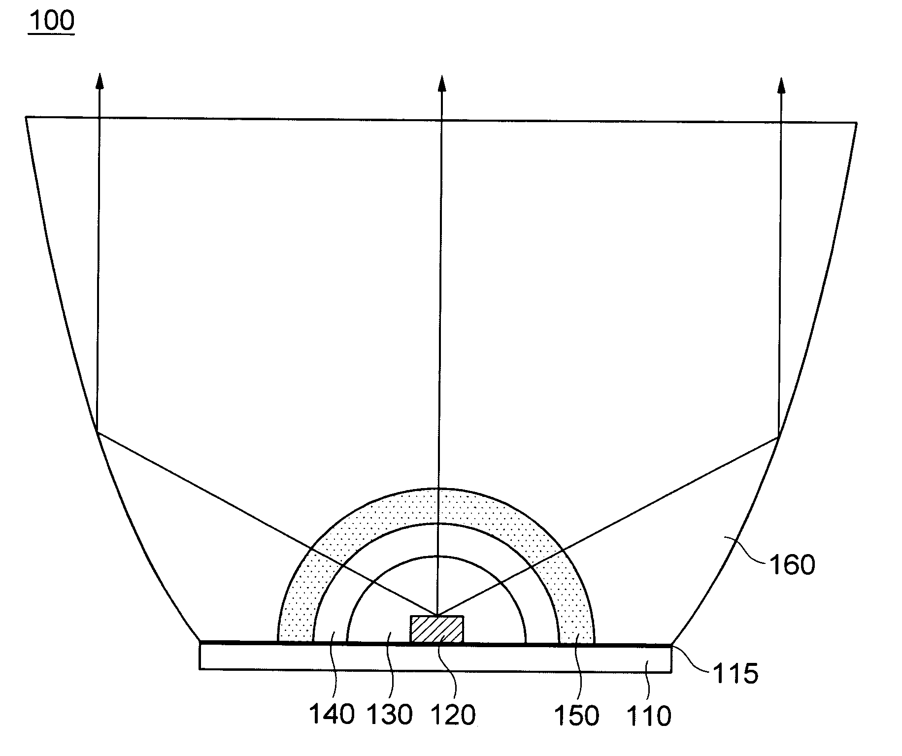
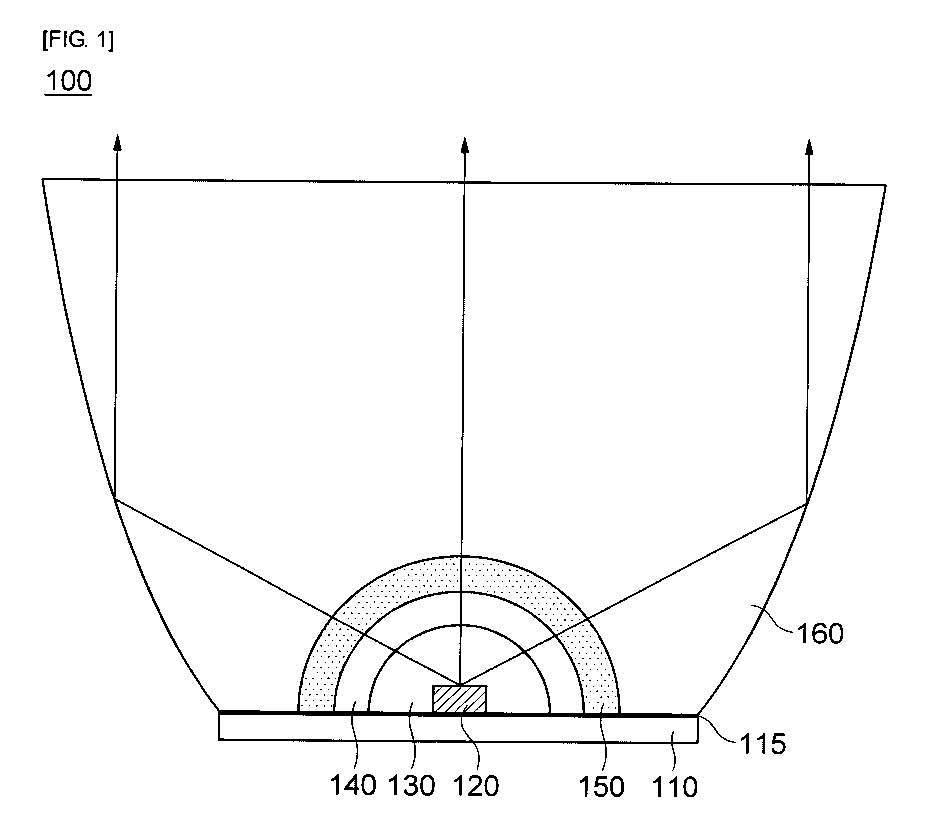
[0036]FIG. 1 is a schematic cross-sectional view of a white LED lighting apparatus using a white LED according to the invention.

[0037]As shown in FIG. 1, the white LED lighting apparatus 100 according to the invention includes a substrate 110, an LED chip 120 mounted on the substrate 110, a fluorescence reflecting layer 140 formed on the LED chip 120, and a phosphor layer 150 formed on the fluorescence reflecting layer 140.

[0038]A reflecting body 1...


PUM


Abstract

Provided is a white LED including a substrate having a reflecting body provided thereon; an LED chip mounted on the substrate; a fluorescence reflecting layer formed on the LED chip; and a phosphor layer formed on the fluorescence reflecting layer and having a higher refractive index than the fluorescence reflecting layer.

Description

CROSS-REFERENCE TO RELATED APPLICATIONS[0001]This application claims the benefit of Korean Patent Application No. 10-2008-0031147 filed with the Korea Intellectual Property Office on Apr. 4, 2008, the disclosure of which is incorporated herein by reference.BACKGROUND OF THE INVENTION[0002]1. Field of the Invention[0003]The present invention relates to a white light emitting diode (LED) and a lighting apparatus using the same.[0004]2. Description of the Related Art[0005]An LED is referred to as a device which generates minority carriers (electrons or holes) injected by using the p-n junction structure of semiconductor and emits light by recombining the minority carriers. As for the LED, a red LED using GaAsP or the like, a green LED using GaP or the like, and a blue LED using InGaN / AlGaN double hetero structure are provided.[0006]The LED has low power consumption and a long lifespan. Further, the LED can be installed in a narrow space, and has high resistance to vibration. The LED is...

Claims


Application Information

Patent Timeline
Patent Type & Authority Applications(United States)
IPC IPC(8): H01L33/00H01L33/44H01L33/50
CPCH01L33/50H01L33/44F21K9/64F21K9/69F21Y2115/10
Inventor YUN, MI JEONGMIN, KYEONG IK
Owner SAMSUNG ELECTRONICS CO LTD
Why Eureka
Try Eureka