Low heat leak, high torque power shaft for cryogenic machines

Inactive Publication Date: 2009-10-08
GOODZEIT CARL L
View PDF31 Cites 9 Cited by
  • Summary
  • Abstract
  • Description
  • Claims
  • Application Information

AI Technical Summary

Benefits of technology

[0008]The object of this invention is to provide an interface design that enables the transmission of large amounts of torque through the shafts of electric machines that use superconducting rotors, while lowering heat leak from the environment to the cryogenic system. The reduced heat leakage supports the cryogenic operating temperatures used with the superconducting materials. The invention is for a rotor shaft that serves as an extension to the rotor shaft of a cryogenic machine and substantially reduces the heat transmitted into the cryogenic environment of the machine. This extension rotor shaft uses a nested set of elongated cylindrical members, materials with a low thermal conductivity, members comprising materials of high structural strength, and optional intermediate temperature heat sinks, in a thermal insulating vacuum space. The invention allows the rotating shaft to operate at high torque with low heat leak and yet sustain the stresses encountered in the shaft without compromising the strength or rotation of the shaft. The invention reduces the heat flow through a rotating shaft by using a plurality of nested series-connected structural members for a given temperature difference between

Problems solved by technology

Any seals and bearings used in the rotor system can also degrade the cryogenic environment because of wear and friction.
The dynamic stability of a rotating system is difficult to maintain, especially when the rotating system contains a free flowing cryogenic fluid associated with a rotating shaft in a superconducting machine.
Rotating cryogenic leak-tight seals have inherent problems associated with them, such as surface friction.
Over time, the friction on these surfaces of the seal will cause it to wear away and eventua

Method used


Image

  • Low heat leak, high torque power shaft for cryogenic machines
  • Low heat leak, high torque power shaft for cryogenic machines
  • Low heat leak, high torque power shaft for cryogenic machines

Examples


first embodiment

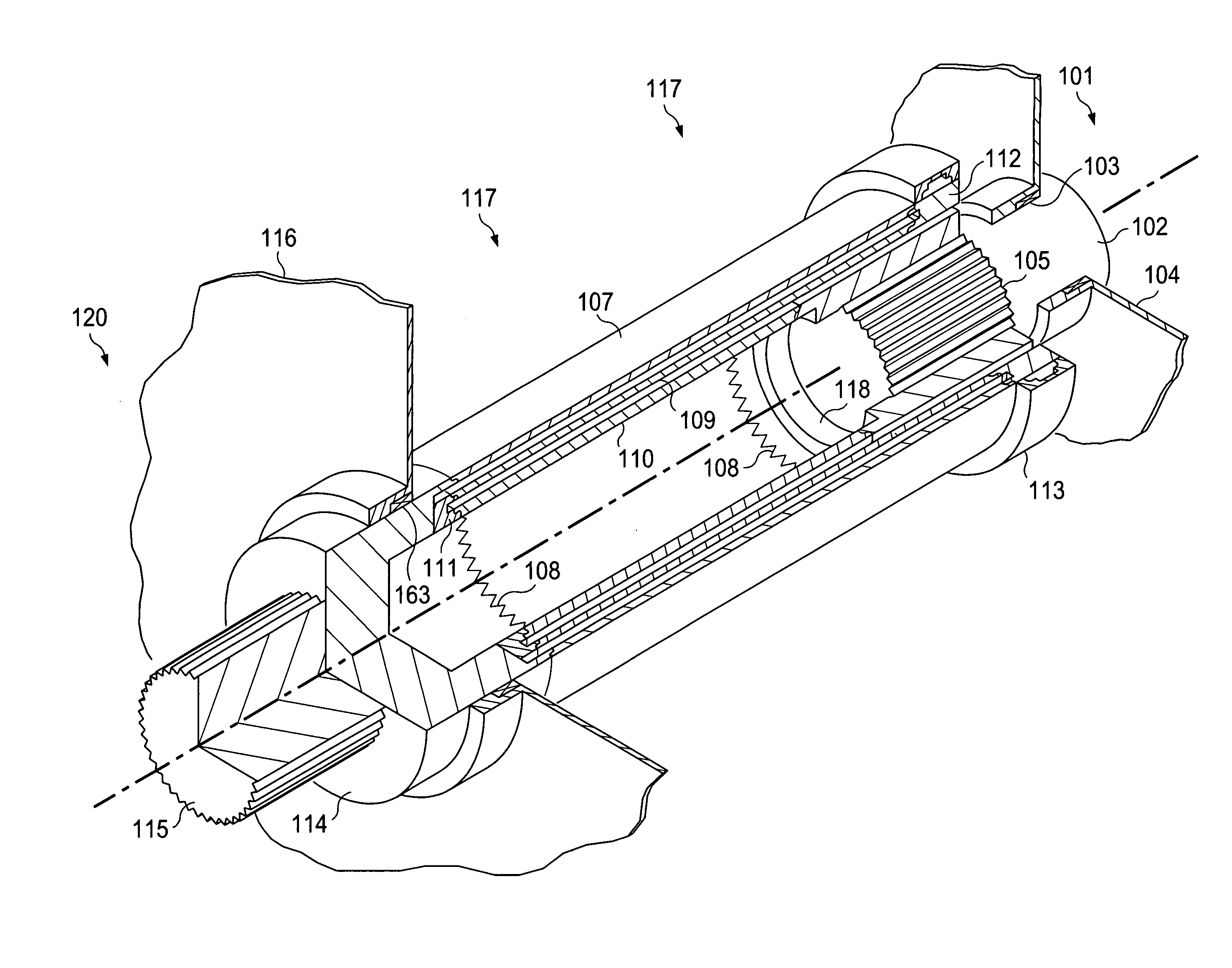
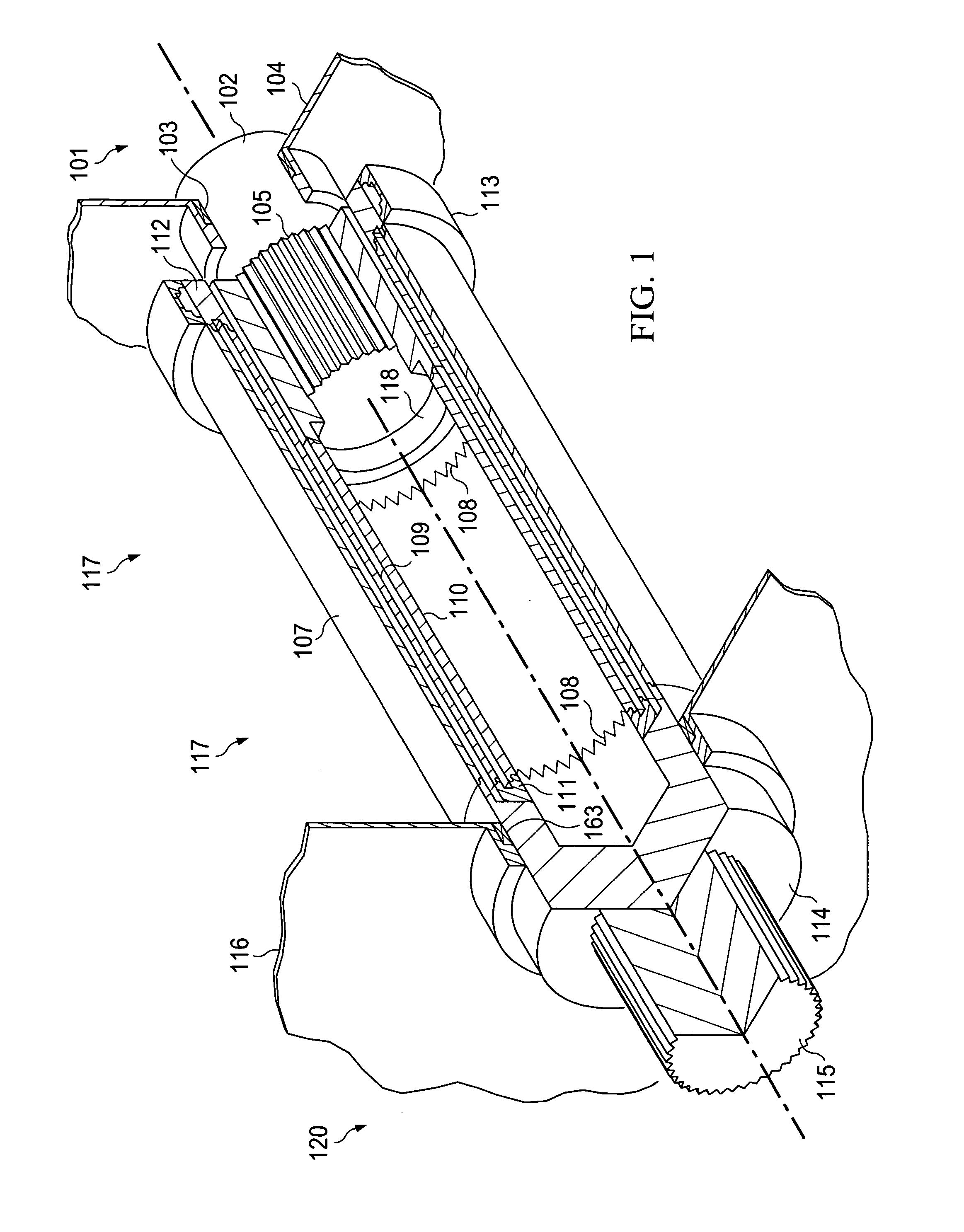
[0022]FIG. 1 is a low heat leak, high torque capacity shaft extension. The embodiment of FIG. 1 uses 3 concentric cylinders, with the coldest cylinder layer of the shaft extension being the inner-most layer 110.

[0023]The rotor shaft 102 of the superconducting machine extends out of the cryogenic environment 101 through the enclosure 104 into the insulating vacuum space 117 where the shaft extension is located. A bearing and seal assembly 103 is required to prevent leakage of the cryogen into the insulating vacuum space 117 and provide a load carrying bearing to support the shaft 102 and allow it to rotate freely. In order to transmit the large amount of torque required for operation, the end of the rotor shaft 102 of the superconducting machine may be configured as a splined connection 105 that engages the adapter hub 118 of the shaft extension.

[0024]The inner most (coldest) cylinder 110 is connected to this adapter hub 118. The series connection between the inner most (coldest) cyl...

second embodiment

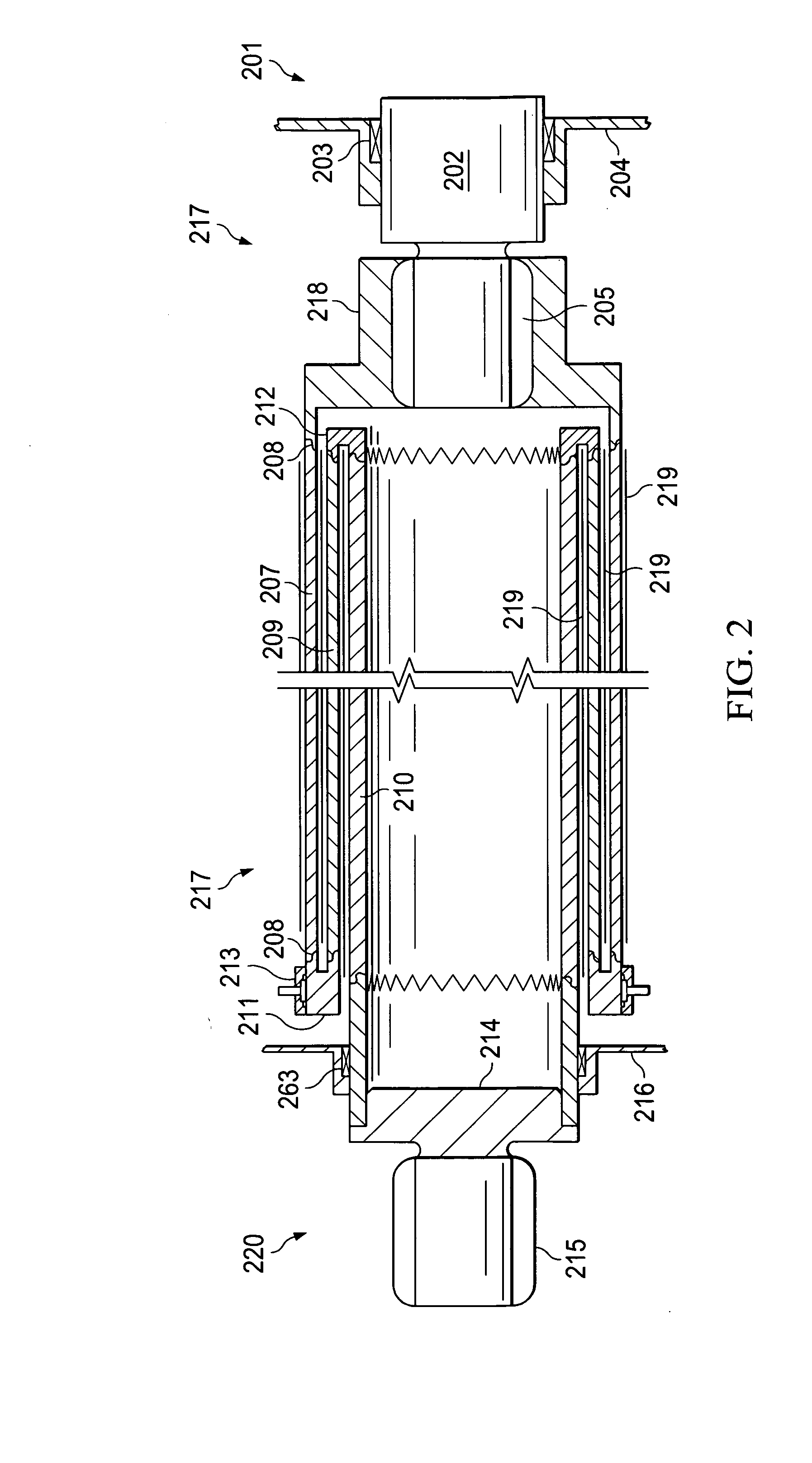
[0027]FIG. 2 is the present invention. It uses 3 concentric cylinders, with the coldest cylinder layer of the shaft extension as the outer layer 207.

[0028]The rotor shaft 202 of the superconducting machine extends out of the cryogenic environment 201 through the enclosure 204 into the insulating vacuum space 217. A bearing and seal assembly 203 is required to prevent leakage of the cryogen into the insulating vacuum space 217 and provide a load carrying bearing to support the shaft 202 and allow it to rotate freely. In order to transmit the large amount of torque required for operation, the shaft end of the superconducting machine may be configured as a splined connection 205 that engages with splines of the adapter hub 218 on the shaft extension.

[0029]The coldest (outer) layer 207 of concentric cylinders is connected to the adapter hub 218 and makes a series connection to the middle layer cylinder 209 at the connector ring 211. A connector ring 212 makes the series connection betwe...


PUM


Abstract

A shaft assembly and method for reducing the heat leak into the cryogenic region of a superconducting electrical machine comprising a rotor shaft extension assembly capable of transmitting large amounts of torque with substantially increased thermal impedance. The shaft assembly contains a plurality of concentric structural cylinders composed of high strength, low thermal conductivity structural materials. The structural cylinders are connected in series by means of welded joints or strong interlocking “finger” connections, in such a way that the coldest cylinder is connected to the cryogenic machine. An optional intermediate heat sink that allows the shaft extension member to rotate freely within the confines of the heat sink further reduces the heat leak into the cryogenic environment. Splined adapter hubs are typically used to connect the cylinder assembly to the rotor of the superconducting machine and the external device.

Description

RELATED APPLICATION DATA[0001]This application is related to Provisional Patent Application Ser. No. 61 / 041,673 filed on Feb. 4, 2008, and priority is claimed for these earlier filings under 35 U.S.C. §119(e). The Provisional Patent Application is also incorporated by reference into this utility patent application.TECHNICAL FIELD OF THE INVENTION[0002]This invention relates to a cryogenic machine heat sink associated with a rotating shaft assembly.BACKGROUND OF THE INVENTION[0003]In order to get optimal performance from a superconducting electrical machine, it is important to minimize the heat leak into the system in order to maintain the required cryogenic environment. The rotating shafts that connect the cryogenic electrical machines to non-cryogenic external devices are potential major paths for transmitting heat from the external environment into the cryogenic system. Any seals and bearings used in the rotor system can also degrade the cryogenic environment because of wear and f...

Claims


Application Information

Patent Timeline
IPC IPC(8): H02K9/24
CPCH02K7/003Y02E40/62H02K55/00Y02E40/60
Inventor GOODZEIT, CARL L.
Owner GOODZEIT CARL L
Why Eureka
Try Eureka