
Method and apparatus for torque ripple reduction

a technology of torque ripple and torque ripple, which is applied in the direction of electronic commutation motor control, motor/generator/converter stopper, dynamo-electric converter control, etc., can solve the problems of speed ripple or excite driveline resonance, torque ripple will exist, torque ripple can have certain adverse effects, etc., and achieve the effect of reducing torque and reducing torque rippl

Active Publication Date: 2009-10-08
DAIMLER AG +3
View PDF2 Cites 88 Cited by
  • Summary
  • Abstract
  • Description
  • Claims
  • Application Information

AI Technical Summary

Benefits of technology

[0005]A controller is provided for generating reduced torque ripple pulse width modulated operational control signals in a permanent magnet motor system. The controller includes a harmonic cancellation synchronous regulator block for receiving a torque command and generating a tor

Problems solved by technology

However, due to practical design constraints of the AC motor, torque ripple will exist even with purely sinusoidal stator current excitation.
However, there exists a trade-off between torque ripple and torque density of the AC motor.
Depending upon the application, torque ripple can have certain adverse affects.
For example, the torque ripple can cause speed ripple or excite driveline resonances.
In the case of an electric or hybrid vehicle, this can result in vehicle oscillations which are a disturbance to the occupants.
Additionally, stator vibrations and acoustic noise can be generated by the radial forces imposed on the stator laminations.
Mitigating acoustic noise by passive means, such as the addition of structural reinforcement or sound dampening materials, can be a costly and undesirable solution.

Method used


Image

  • Method and apparatus for torque ripple reduction
  • Method and apparatus for torque ripple reduction
  • Method and apparatus for torque ripple reduction

Examples


Embodiment Construction

[0028]The following detailed description is merely exemplary in nature and is not intended to limit the invention or the application and uses of the invention. Furthermore, there is no intention to be bound by any expressed or implied theory presented in the preceding technical field, background, brief summary or the following detailed description.

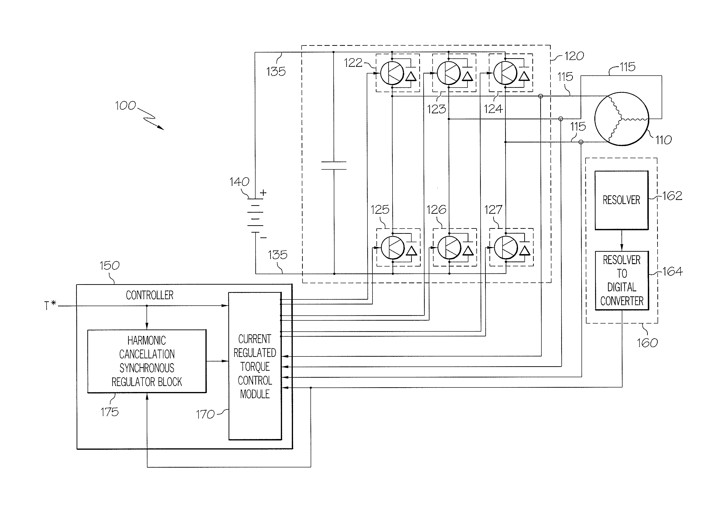
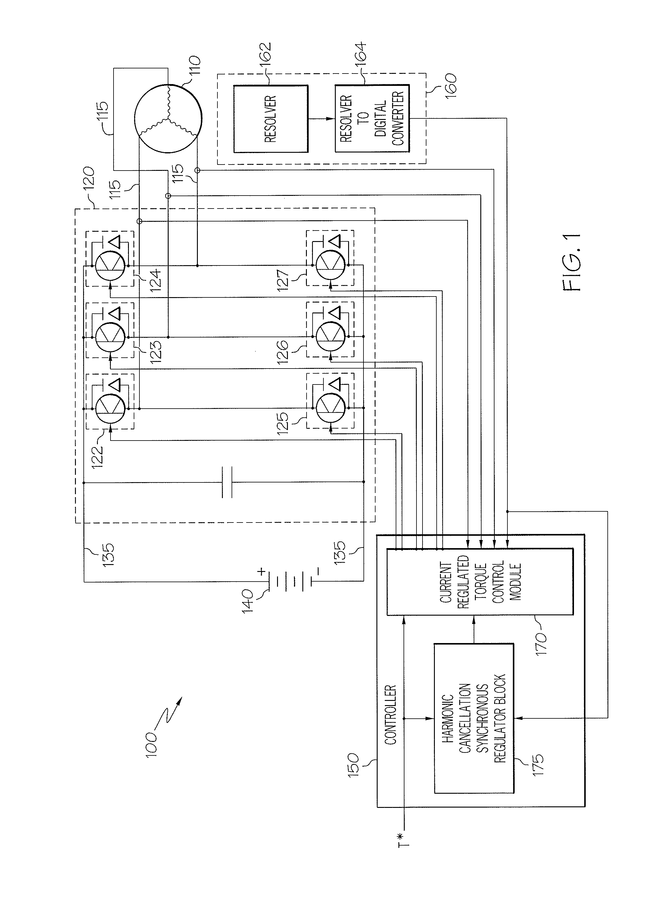
[0029]Referring to FIG. 1, an electric motor system 100 in accordance with an embodiment of the present invention includes a three-phase alternating current (AC) synchronous electric machine 110, such as an internal permanent magnet (IPM) motor, which operates in response to signals from an inverter 120. The inverter 120 providing electric control for the electric motor 110 is connected between direct current (DC) bus lines 135 of a power source 140. The inverter 120 includes switches 122, 123, 124, 125, 126, 127, each of the switches including a transistor such as an Insulated Gate Bipolar Transistor (IGBT) connected in parallel with an a...


PUM


Abstract

Methods and apparatus are provided for reducing torque ripple in a permanent magnet motor system comprising a permanent magnet motor coupled to an inverter. The method comprises the steps of receiving a torque command, generating a torque ripple reduction signal in response to the torque command, modifying operational control signals in response to the torque ripple reduction signal to generate reduced ripple operational control signals, and providing the reduced ripple operational control signals to the inverter for control of the permanent magnet motor.

Description

TECHNICAL FIELD[0001]The present invention generally relates to alternating current (AC) motor drive systems, and more particularly relates to a method and apparatus for torque ripple reduction in AC motor drive systems.BACKGROUND OF THE INVENTION[0002]The primary purpose of an alternating current (AC) motor drive is to provide a requested torque to the motor shaft. Ideally, the provided torque is constant with no distortion or ripple. Toward this end, the typical motor drive attempts to provide a balanced set of purely sinusoidal currents to the motor stator windings. However, due to practical design constraints of the AC motor, torque ripple will exist even with purely sinusoidal stator current excitation. Motor designers usually attempt to minimize the torque ripple generated by the AC motor. This can be accomplished by paying particular attention to design aspects such as winding configuration, stator tooth geometry, rotor barrier geometry, and rotor skewing. However, there exis...

Claims


Application Information

Patent Timeline
IPC IPC(8): H02P6/10H02P27/08
CPCH02P6/10H02P27/08H02P21/06
Inventor SCHULZ, STEVEN E.MILLER, JOHN P.RAHMAN, KHWAJA M.LEE, SOO-YEOL
Owner DAIMLER AG
Learn More