

Coaxial cable
a technology of coaxial cable and shielding layer, which is applied in the direction of power cables, cables, insulated conductors, etc., can solve the problems of less strength of conducting wire and shielding layer made of metal, signal decay during transmission, and skin effect of conducting wir
- Summary
- Abstract
- Description
- Claims
- Application Information
AI Technical Summary
Benefits of technology
Problems solved by technology
Method used
Image

Examples
first embodiment
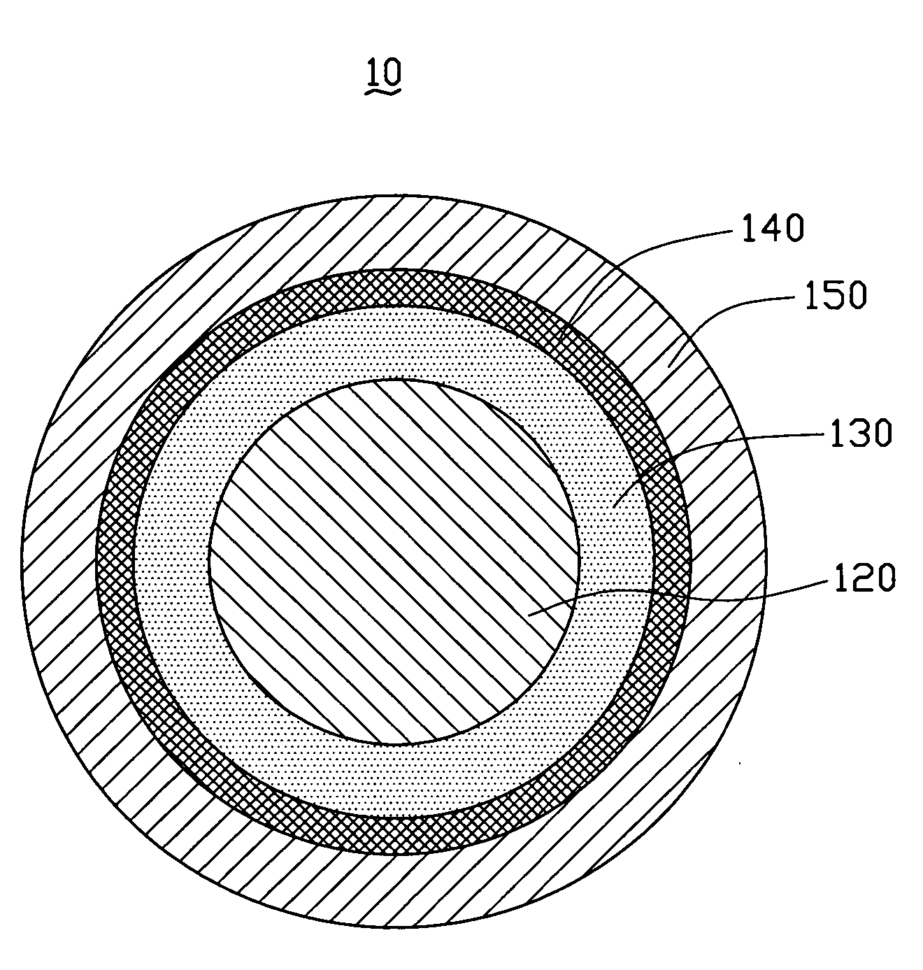
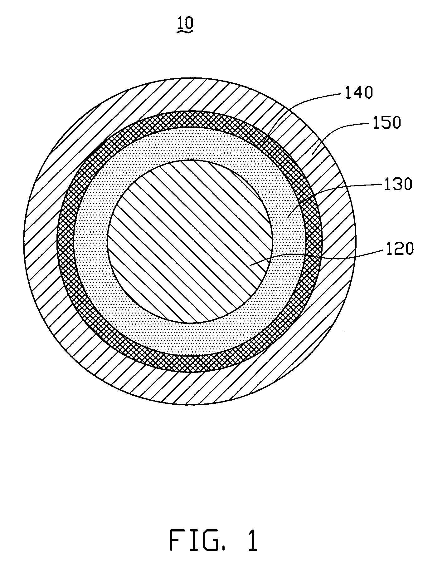
[0018]Referring to FIG. 1, a coaxial cable 10 includes a core 120, an insulating layer 130, a shielding layer 140, and a sheathing layer 150. The insulating layer 130 wraps the core 120. The shielding layer 140 wraps the insulating layer 130. The sheathing layer 150 wraps the shielding layer 140. The core 120, the insulating layer 130, the shielding layer 140, and the sheathing layer 150 are coaxial.
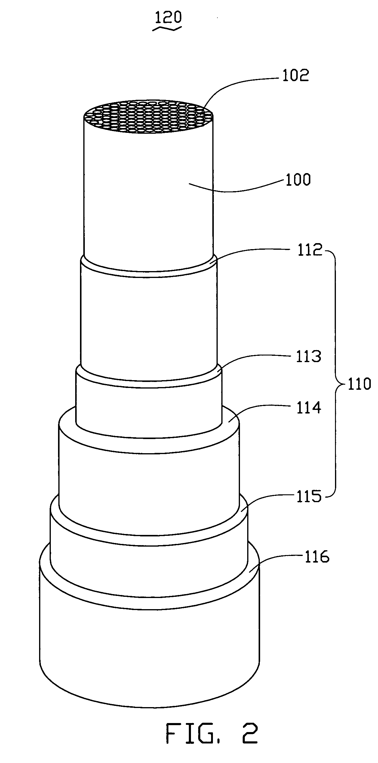
[0019]Referring also to FIG. 2, the core 120 includes a carbon nanotube wire-like structure 100, a conductive coating 110, and a strengthening layer 116. The conductive coating 110 wraps the carbon nanotube wire-like structure 100 and comprises at least one conductive layer 114. The strengthening layer 116 wraps the conductive coating 110. The carbon nanotube wire-like structure 100 includes one or a plurality of carbon nanotube wires 102. The diameter of the core 120 is about 10 microns to about 1 centimeter. Here, the carbon nanotube wire-like structure 100 includes a plurality of car...
second embodiment
[0033]Referring to FIG. 6, a coaxial cable 30 is shown. The coaxial cable 30 includes a plurality of cores 320, a plurality of insulating layers 330, a shielding layer 340, and a sheathing layer 350. Each core 320 is wrapped by a corresponding insulating layer 330. The shielding layer 340 wraps the plurality of insulating layers 330 therein. The sheathing layer 350 wraps the shielding layer 340. Between the shielding layer 340 and the insulating layer 330, insulating material is filled.
third embodiment
[0034]Referring to FIG. 7, a coaxial cable 40 is shown. The coaxial cable 40 includes a plurality of cores 420, a plurality of insulating layers 430, a plurality of shielding layers 440, and a sheathing layer 450. Each insulating layer 430 wraps a corresponding core 420. Each insulating layer 430 is wrapped by a corresponding shielding layer 440.
[0035]Here, each shielding layer 440 can shield each core 420. The shielding layers 440 are configured to avoid interference coming from outside factors, and avoid interference amongst the cores of the plurality of cores 420.
[0036]The coaxial cable 10, 30, 40 provided in the embodiments has the following superior properties. Since the core of the coaxial cable 10, 30, 40 include a carbon nanotube wire-like structure 100 and at least one layer of the conductive material. The carbon nanotube wire-like structure includes a plurality of carbon nanotubes orderly arranged, and a thickness of the at least one layer of the conductive material is ju...
PUM
 Abstract
Description
Claims
Application Information