

Multiband folded loop antenna
- Summary
- Abstract
- Description
- Claims
- Application Information
AI Technical Summary
Benefits of technology
Problems solved by technology
Method used
Image

Examples
second embodiment
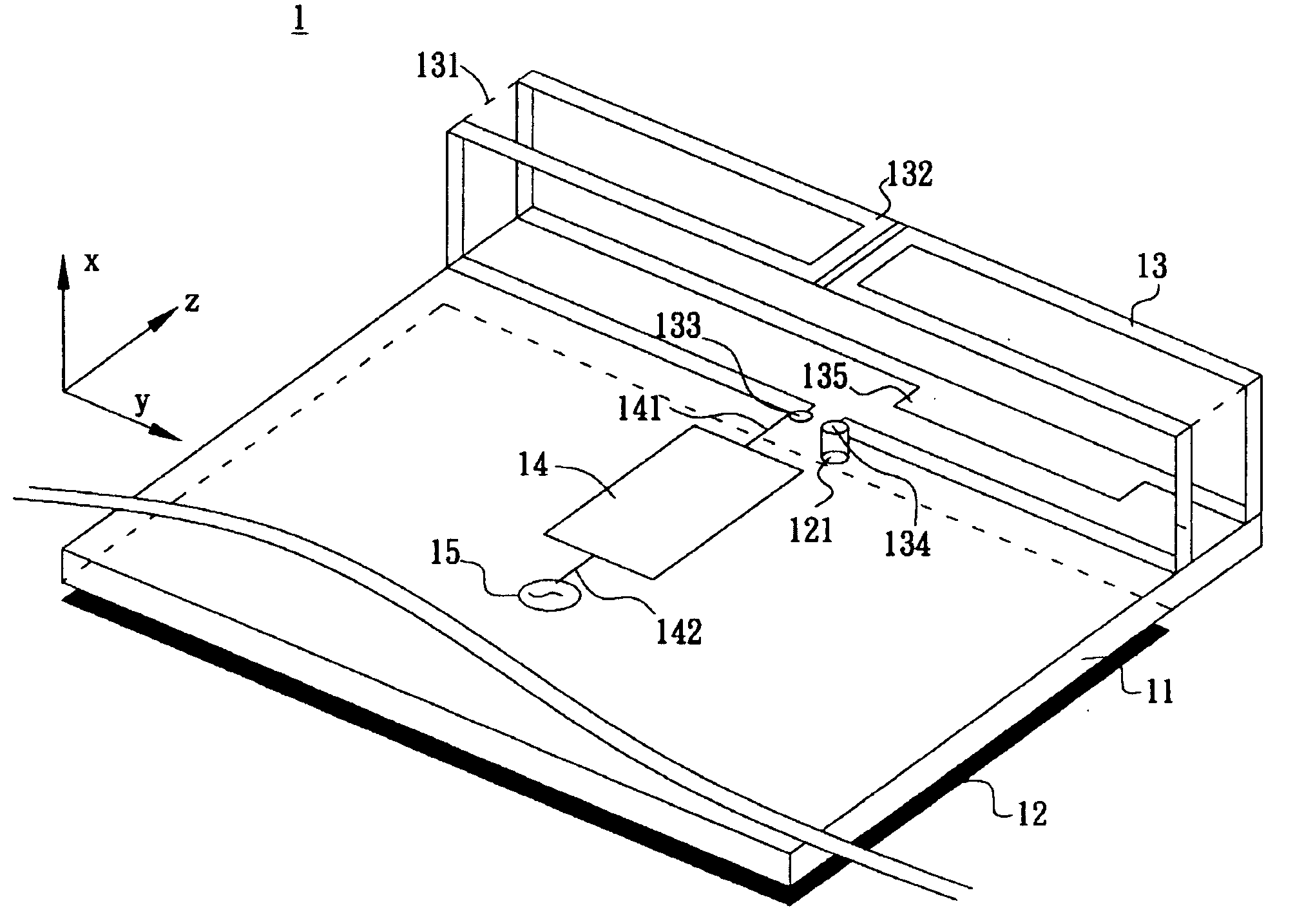
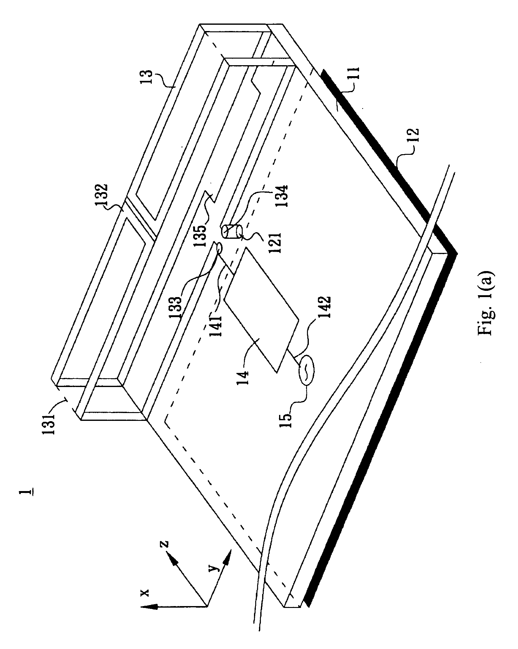
[0025]FIG. 2 illustrates a multiband folded loop antenna 2 according to the present invention. The antenna 2 comprises a dielectric substrate 11, a ground plane 12, and a radiating portion 13. The ground plane 12 has a grounding point 121, and is located on the dielectric substrate 11. The radiating portion 13 comprises a supporter 131, a loop strip 132, and a tuning patch 135. The loop strip 132 of the radiating portion 13 has a length about half wavelength of the lowest resonant frequency of the antenna, and has a feeding end 133 and a grounding end 134. The feeding end 133 is electrically connected to a signal source 15, and the grounding end 134 is electrically connected to the grounding point 121 of the ground plane 12. The loop strip 132 is folded into a three-dimensional structure and supported by the supporter 131. The tuning patch 135 of the radiating portion 13 is electrically connected to the loop strip 132.
[0026]Preferably, the dielectric substrate 11 can be a system cir...
first embodiment
[0029]FIG. 4 illustrates the radiation field patterns of the antenna 1 according to the present invention when providing operation covering GSM 850 / 900 bands, wherein FIG. 4(a) illustrates the radiation field patterns at a frequency of 859 MHz and FIG. 4(b) illustrates the radiation field patterns at a frequency of 925 MHz. The low frequency band 21 of the antenna 1 covering these operation bands is of the 0.5-wavelength resonant mode. As shown in FIG. 4, the radiation field patterns of the 0.5-wavelength resonant mode resonating on the loop strip is similar to the radiation field patterns of the conventional monopole antenna or planar antenna resonating at the same frequencies.
[0030]FIG. 5 illustrates the radiation field patterns of the antenna 1 according to the first embodiment of the present invention when providing operation covering GSM 1800 / 1900 / UMTS bands, and FIG. 5(a) illustrates the radiation field patterns at a frequency of 1795 MHz, FIG. 5(b) illustrates the radiation f...
PUM
 Abstract
Description
Claims
Application Information