Laser light source, image display apparatus, and processing apparatus

a technology of laser light source and image display device, which is applied in the direction of laser details, instruments, light demodulation, etc., can solve the problems of reducing the output of wavelength-converted light emitted from the laser light source over time, and the difficult oscillation of the use of semiconductor lasers, so as to suppress the expansion and contraction of spontaneous polarization, suppress the effect of reducing output and suppressing the increase of optical absorption over tim

Inactive Publication Date: 2009-10-15
PANASONIC CORP
View PDF10 Cites 17 Cited by
  • Summary
  • Abstract
  • Description
  • Claims
  • Application Information

AI Technical Summary

Benefits of technology

[0025]According to the foregoing structure, the insulation layer having electric resistivity of not less than 1×10⁸ Ω·cm is formed on the element surface of the wavelength conversion element, in a direction of crossing the polarization direction of the periodically poled structure. With this structure, in a portion where the insulation layer is formed, a direct contact between the holding member and the element surface of the wavelength conversion element. In a case where spontaneous polarization within a ferroelectric crystal serving as the wavelength conversion element expands and contracts, charges are generated due to voltage rise effect on the element surface of the wavelength conversion element in a portion where the holding member is not in direct contact. An electric field produced by the charges thus generated causes the polarization wall to generate setoff stress to suppress expansion and contraction of the spontaneous polarization. It thus becomes possible to suppress an increase in the optical absorptance over time within the wavelength conversion element, which in turn makes it possible to suppress a reduction in output over time of a wavelength-converted laser light obtained through wavelength conversion by the wavelength conversion element.

Problems solved by technology

A wavelength conversion element has been studied extensively, in particular, for a green laser, oscillations of which with the use of a semiconductor laser are difficult.
However, in a case where the periodically poled structure is formed in a ferroelectric crystal and a laser light source employs this ferroelectric crystal as a wavelength conversion element, a problem arises in that an output of wavelength-converted light emitted from this laser light source is reduced over time.

Method used


Image

  • Laser light source, image display apparatus, and processing apparatus
  • Laser light source, image display apparatus, and processing apparatus
  • Laser light source, image display apparatus, and processing apparatus

Examples


first embodiment

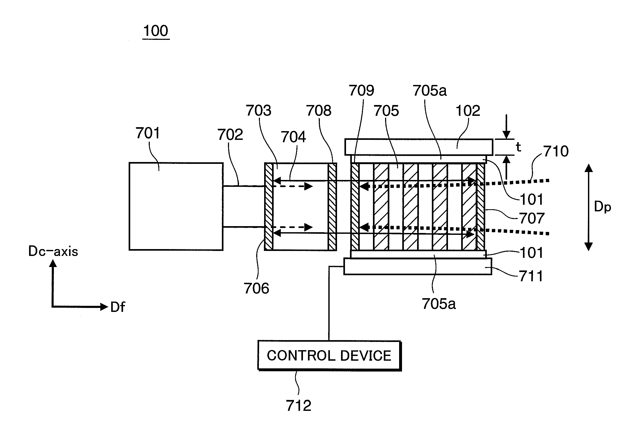
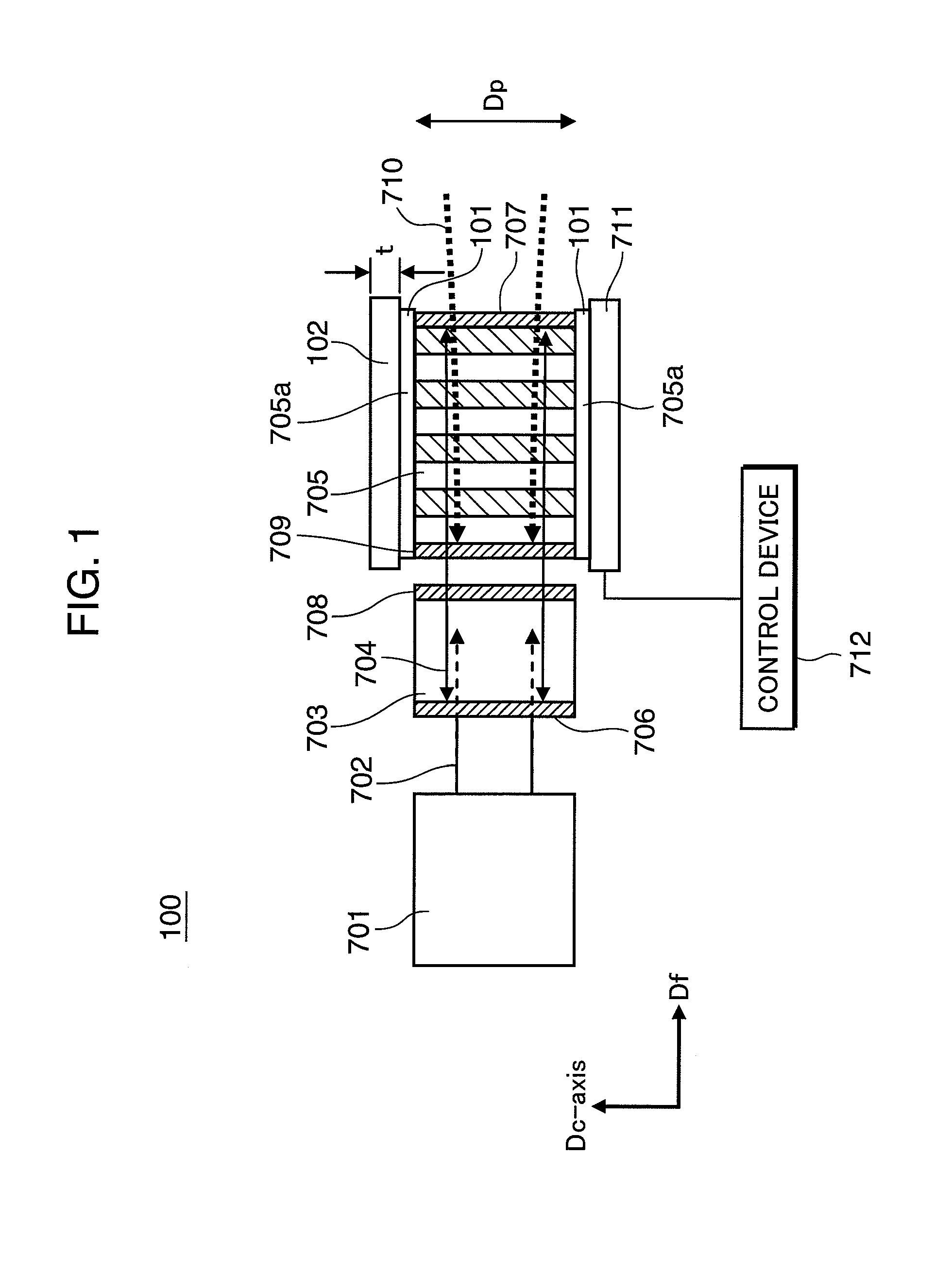
[0045]A laser light source according to one embodiment of the invention will be described in the following with reference mainly to FIG. 1 through FIG. 4, FIG. 6A, and FIG. 6B. As will be described in detail below, the laser light source in accordance with the present embodiment is capable of suppressing a decrease in output of a wavelength-converted laser light over time.

[0046]Firstly, results of comparative experiments using a conventional laser light source will be explained to ease the explanations of the laser light source in accordance with the present embodiment.

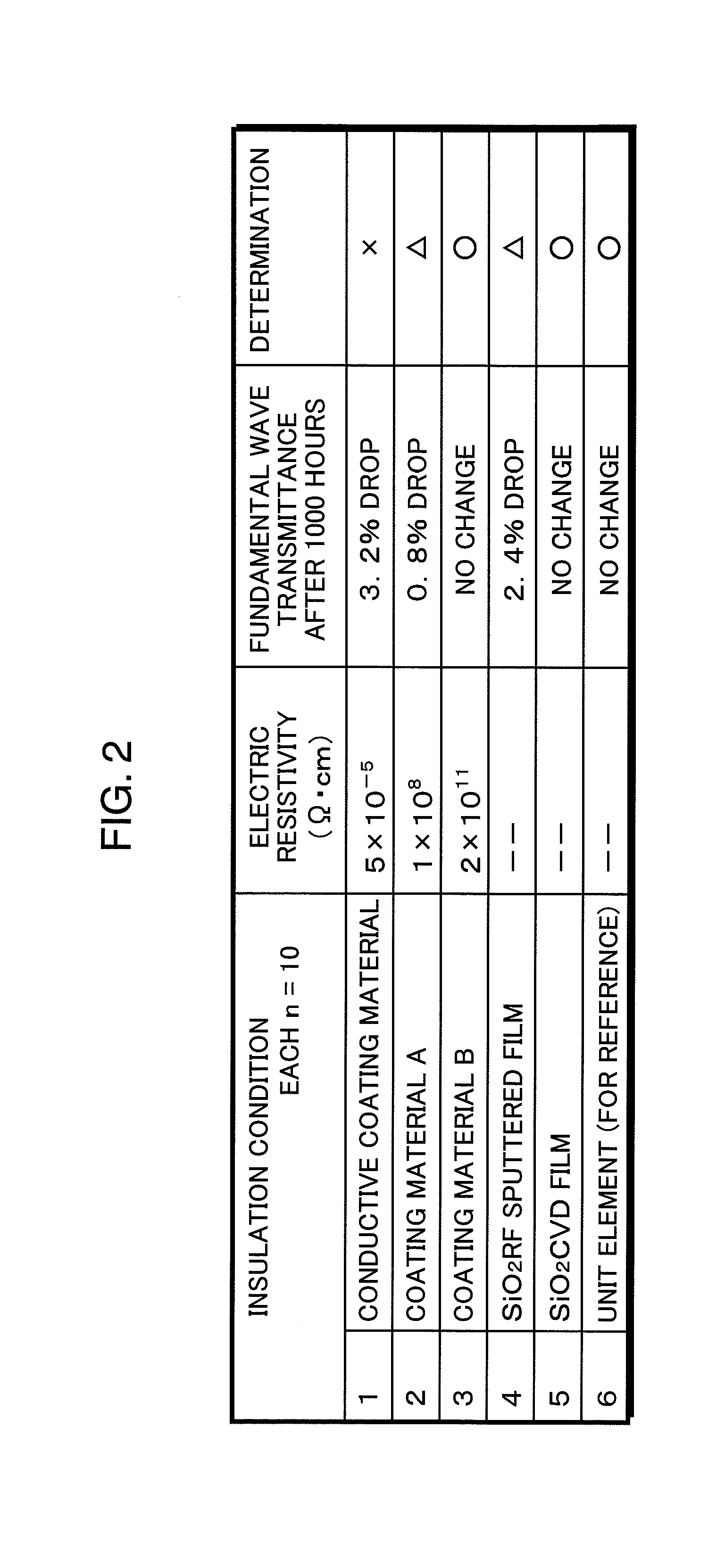
[0047]As a comparative experiment using the conventional wavelength conversion laser light source 700 shown in FIG. 16, the wavelength conversion laser light source 700 was pulse-driven for 1000 hours under the conditions that the peak output was 1 W, the repeating frequency was 100 kHz, and the duty was 50%. As shown in FIG. 17, it becomes obvious from the results of this comparative experiment that an output power o...

second embodiment

[0119]Another embodiment of the invention will be described in the following with reference to the drawings.

[0120]Because a wavelength conversion laser light source of the present embodiment has a basic structure which is in common with the wavelength conversion laser light source of the first embodiment above, a characteristic portion alone will be described. Members having the same structures and functions will be designated by the same reference numerals, and the descriptions thereof shall be omitted where appropriate.

[0121]FIG. 5 is an explanatory view schematically showing the structure of a wavelength conversion laser light source 1300 of the present embodiment. The wavelength conversion laser light source 1300 of the present embodiment is an intra-resonator green laser light source as with the counterpart of the first embodiment above.

[0122]The wavelength conversion laser light source 1300 does not include the solid-state laser crystal 703 in the wavelength conversion laser l...

third embodiment

[0128]Still another embodiment of the invention will be described in the following with reference to the drawings.

[0129]Because the wavelength conversion laser light source of the present embodiment has a basic structure which is in common with the wavelength conversion laser light source of the first embodiment above, a characteristic portion alone will be described. Members of similar configurations are labeled with like reference numerals and descriptions of such members are omitted where appropriate.

[0130]As will be described below, a wavelength conversion laser light source of the present embodiment includes a wavelength conversion element capable of lessening a problem that occurs in a case where high-output wavelength conversion in a visible light region exceeding several W is performed.

[0131]A problem to be solved for a wavelength conversion element made of an LN or LT crystal is to prevent a phenomenon (photorefractive phenomenon) called optical damage caused by a change of...


PUM


Abstract

A laser light source includes a fundamental laser generator that generates a fundamental laser light, a wavelength conversion element that is made of a ferroelectric crystal with a periodically poled structure and converts the fundamental laser light to a laser light having a different wavelength, a holding member that holds at least a part of an element surface of the wavelength conversion element that crosses a polarization direction of the periodically poled structure, and an insulation layer that is provided between the holding member and the element surface. Electric resistivity of the insulation layer is 1×10⁸ Ω·cm or higher.

Description

BACKGROUND OF THE INVENTION[0001]1. Field of the Invention[0002]The present invention relates to a laser light source provided with a quasi phase matching wavelength conversion element that performs wavelength conversion by utilizing the nonlinear optical effect, and an image display apparatus and a processing apparatus employing such laser light source.[0003]2. Description of the Related Art[0004]A ferroelectric crystal having formed therein a periodically poled region is used for a wavelength conversion element that exploits the inversion of nonlinear polarization, an optical deflector that exploits a prism-shaped or lens-shaped inversion structure, and so forth.[0005]As a method for forming a periodically poled structure in a ferroelectric crystal, a method shown, for example, in FIG. 15, is adopted. Specifically, first polarization directions of a ferroelectric crystal 201 are aligned to a given direction, and then, with the use of a power supply 205 and a partially formed elect...

Claims


Application Information

Patent Timeline
Patent Type & Authority Applications(United States)
IPC IPC(8): H01S3/10G02B26/08
CPCG02F1/0305G02F1/3775H01S3/109H01S3/09415G02F2203/60
Inventor KUSUKAME, KOICHIFURUYA, HIROYUKIMIZUUCHI, KIMINORISUGITA, TOMOYAMORIKAWA, AKIHIROHORIKAWA, NOBUYUKIYAMAMOTO, KAZUHISAKADOWAKI, SHINICHI
Owner PANASONIC CORP
Why Eureka
Try Eureka