Negative Electrode Active Material for Electrical Device and Electrical Device Using the Same

a technology of active materials and negative electrodes, which is applied in the direction of negative electrodes, electrochemical generators, cell components, etc., can solve the problems of large expansion and shrinkage of negative electrodes, difficult to obtain capacity and energy density, and difficult to obtain the capacity and energy density of 372 mah/g or more, etc., to achieve the enhancement of the forming ability of the amorphous (amorphous or low crystalline si) phase, the effect of decreasing the modal radius

Active Publication Date: 2019-06-06
NISSAN MOTOR CO LTD
View PDF3 Cites 0 Cited by
  • Summary
  • Abstract
  • Description
  • Claims
  • Application Information

AI Technical Summary

Benefits of technology

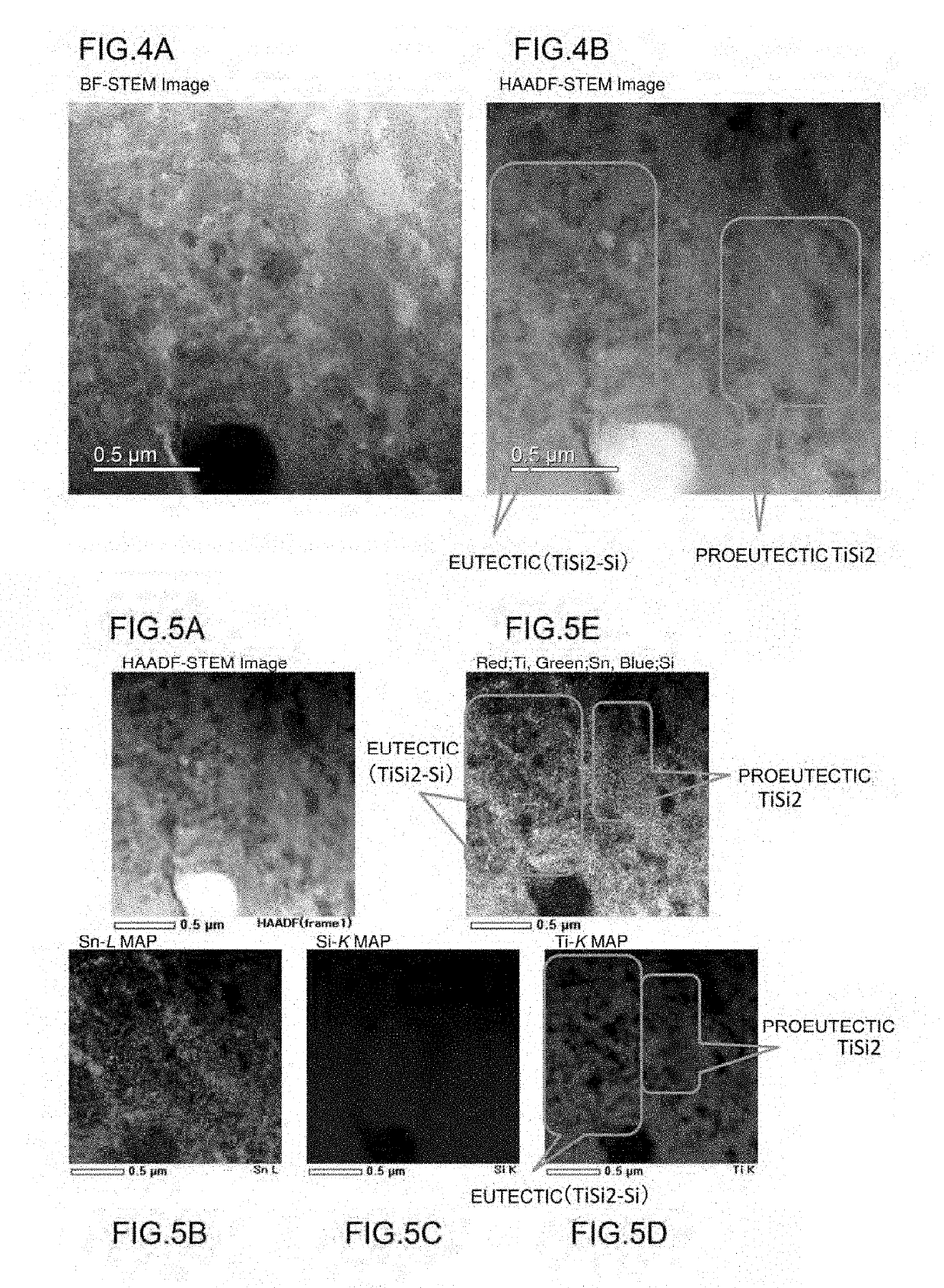
[0022]In the silicon-containing alloy constituting the negative electrode active material according to the present invention, it is possible to obtain an alloy having a particular microstructure by adding a small amount of Al to a Si—Sn-M (hereinafter, described using Ti as an example) alloy having a particular composition. Specifically, the microstructure has a first phase containing a silicide of a transition metal M (Ti) as a main component and a second phase containing Sn and Al in part and amorphous or low crystalline Si as a main component and a part of the microstructure is composed of a plurality of the first phases which are independent and a part of the microstructure has a eutectic structure composed of the first phase and the second phase. By this, the silicon-containing alloy has actions that 1. a silicide of a transition metal M, particularly that of Ti (TiSi2) can be refined (the modal radius of the independent first phases can be decreased), 2. the proportion of Si in the eutectic can be increased, and 3. forming ability of the amorphous (amorphous or low crystalline Si) phase can be enhanced. For these reasons, it is possible to suppress the expansion of Si during charge and discharge and to improve the cycle durability by refinement and amorphization.
[0023]Specifically, by adding a small amount of Al to the Si—Sn-M (to be described using Ti as an example) alloy, the microstructure of the alloy has a configuration in which the second phase (Si phase) is eutecticized with the first phase (TiSi2 phase) and the eutectic further enters the gaps between a plurality of independent first phases (TiSi2 phases). In addition, the first phase (TiSi2 phase) is superior to the second phase (a-Si phase) in the hardness and electron conductivity. Hence, the expansion of the second phase (a-Si phase) in the eutectic structure in the charge and discharge process can be suppressed by so-called two step repression that the expansion is repressed by the eutecticized first phase (TiSi2 phase) and further by a plurality of independent first phases (TiSi2 phases). This suppresses the phase transformation (crystallization into Li15Si4) between the amorphous phase and the crystalline phase when Si is alloyed with Li at the time of charge. As a result, expansion and shrinkage of the silicon-containing alloy constituting the negative electrode active material in the charge and discharge process of the electrical device are diminished and the second phase (a-Si phase) can be uniformly reacted as the second phase is eutecticized with the first phase (silicide phase) to be composed of a silicide exhibiting electrical conductivity. As a result, the cycle durability of the electrical device in which the negative electrode active material is used can be improved while the electrical device has a high capacity.

Problems solved by technology

However, in the carbon and graphite-based negative electrode materials, charge and discharge are performed by occlusion of lithium ions into and release of the lithium ions from the graphite crystals and there is thus a disadvantage that it is impossible to obtain a charge and discharge capacity of 372 mAh / g or more of a theoretical capacity to be obtained from LiC6 which is a compound containing lithium in the largest amount.
For this reason, it is difficult to obtain a capacity and an energy density which satisfy the practical level for a vehicle application from carbon and graphite-based negative electrode materials.
However, in the lithium ion secondary battery in which a material to be alloyed with Li is used in the negative electrode, the negative electrode is greatly expanded and shrunk at the time of charge and discharge.
For example, the volume expansion of a graphite material in the case of occluding Li ions is about 1.2 times, but the Si material is transformed from an amorphous state to a crystalline state when Si and Li are alloyed with each other and a large volume change (about 4 times) is caused, and thus there is a problem that the cycle life of the electrode is diminished.
In addition, in the case of a Si negative electrode active material, there is a trade-off relation between the capacity and the cycle durability and there is thus a problem that it is difficult to improve the cycle durability while having a high capacity.

Method used


Image

  • Negative Electrode Active Material for Electrical Device and Electrical Device Using the Same
  • Negative Electrode Active Material for Electrical Device and Electrical Device Using the Same
  • Negative Electrode Active Material for Electrical Device and Electrical Device Using the Same

Examples


example 1

[0384][Fabrication of Silicon-Containing Alloy]

[0385]An alloy seed was set to Si60.0Sn8.1Ti30.1Al1.8 (Si 60.0% by mass-Sn 8.1% by mass-Ti 30.1% by mass-Al 1.8% by mass) and fabricated by a liquid quenching solidification method. Details will be described below. Specifically, an ingot alloy of a silicon alloy (Si 60.0% by mass, Sn 8.1% by mass, Ti 30.1% by mass, and Al 1.8% by mass) was fabricated using a high purity metal Si ingot (5 N), a high purity Sn plate (3 N), a high purity Ti wire (3 N), and a high purity Al shot (3 N) by an arc melting method. The ingot alloy was coarsely pulverized to a diameter of about 2 mm so as to be easily introduced into a quartz nozzle.

[0386]Subsequently, a ribbon-like alloy=rapidly quenched ribbon (ribbon) alloy was fabricated as a Si-containing alloy using the coarsely pulverized powder of the ingot alloy as a mother alloy by a liquid quenching solidification method. Specifically, the mother alloy of Si60.0Sn8.1Ti30.1Al1.8 was placed in a quartz n...

example 2

[0393]A negative electrode active material, a negative electrode, and a lithium ion secondary battery (coin cell) were fabricated by the same method as in Example 1 described above except that the alloy seed was changed to Si64.7Sn5.0Ti29.9Al0.4 (Si 64.7% by mass-Sn 5.0% by mass-Ti 29.9% by mass-Al 0.4% by mass). The thickness of the ribbon-like alloy (rapidly quenched ribbon alloy) thus obtained was 21.5 μm. In addition, the average particle diameter D50 of the Si-containing alloy (negative electrode active material) powder thus obtained was 5.0 μm and D90 was 16.7 μm.

example 3

[0394]A negative electrode active material, a negative electrode, and a lithium ion secondary battery (coin cell) were fabricated by the same method as in Example 1 described above except that the alloy seed was changed to Si64.0Sn4.9Ti30.0Al1.1 (Si 64.0% by mass-Sn 4.9% by mass-Ti 30.0% by mass-Al 1.1% by mass). The thickness of the ribbon-like alloy (rapidly quenched ribbon alloy) thus obtained was 19.5 μm. In addition, the average particle diameter D50 of the Si-containing alloy (negative electrode active material) powder thus obtained was 4.5 μm and D90 was 16.9 μm.


PUM

PropertyMeasurementUnit
compositionaaaaaaaaaa
microstructureaaaaaaaaaa
modal radiusaaaaaaaaaa

Abstract

A negative electrode active material containing a Si-containing alloy having a composition to be represented by Chemical Formula (1): SixSnyMzAlwAa (in Chemical Formula (1) above, M is one or two or more transition metal elements, A is an unavoidable impurity, and x, y, z, w, and a represent values of percentage by mass, where y, z, and w are 2≤y≤10, 25≤z≤35, and 0.3≤w≤3, respectively, and x and a are remainder) is used in an electrical device, providing a means capable of improving the cycle durability of the electrical device such as a lithium ion secondary battery.

Description

TECHNICAL FIELD[0001]The present invention relates to a negative electrode active material for an electrical device and an electrical device using the same. The negative electrode active material for an electrical device and the electrical device using the same according to the present invention are used in a power source for driving a motor of a vehicle such as an electric vehicle, a fuel cell vehicle, or a hybrid electric vehicle and an auxiliary power source as, for example, a secondary battery or a capacitor.BACKGROUND[0002]In recent years, a decrease in the amount of carbon dioxide is ardently desired in order to cope with the air pollution and global warming. In the motor vehicle industry, it is greatly expected that the carbon dioxide emission is decreased by the introduction of electric vehicles (EV) and hybrid electric vehicles (HEV) and the development of electrical devices such as secondary batteries for driving a motor, which hold the key to practical application of thes...

Claims


Application Information

Patent Timeline
Patent Type & Authority Applications(United States)
IPC IPC(8): H01M4/38H01M4/134
CPCH01M4/386H01M4/134H01M2004/027C22C28/00C01P2002/85C01P2004/03C01P2004/04H01M10/0525Y02E60/10H01M4/38
Inventor ARAI, MASAYACHIBA, NOBUTAKAYOSHIOKA, YOUICHIWATANABE, MANABU
Owner NISSAN MOTOR CO LTD
Why Eureka
Try Eureka