
Turbine assembly

Inactive Publication Date: 2009-10-15
ASIA POWER DEV FOUND
View PDF6 Cites 8 Cited by
  • Summary
  • Abstract
  • Description
  • Claims
  • Application Information

AI Technical Summary

Benefits of technology

[0005]The turbine is provided with blades disposed at a predetermined angle so that it can become a dual reaction turbine that alternately harnesses and converts the oscillating flows of the floods and ebbs into rotary torque without swinging around with the direction of the current. The invention further having blades with distinctive aerodynamic contour which increases the turbine's efficiency and sensitivity to slow currents, thus, allowing immediate “start up” at the beginning of every tidal cycle. It facilitates the flow, minimizes the exit-turbulence and it adds buoyancy and efficiency to the turbine.

Problems solved by technology

Numerous methods and devices have already been tested and utilized for harnessing and converting the mechanical (kinetic) energy of oceans into useful electric power, however, their practical implementation had encountered numerous problems on account of its economic and environmental nature.
The hydraulic resistance acting on the blades offsets a part of the effective hydraulic energy obtained by the blades positioned at the lowermost portion of the runner, thereby resulting in an inferior operational efficiency.

Method used


Image

  • Turbine assembly
  • Turbine assembly
  • Turbine assembly

Examples


Embodiment Construction

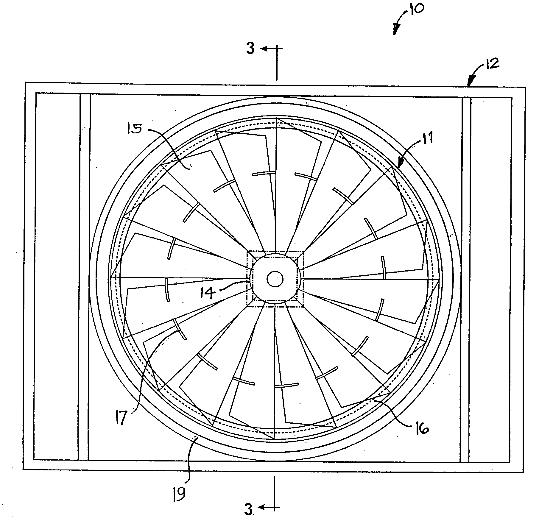
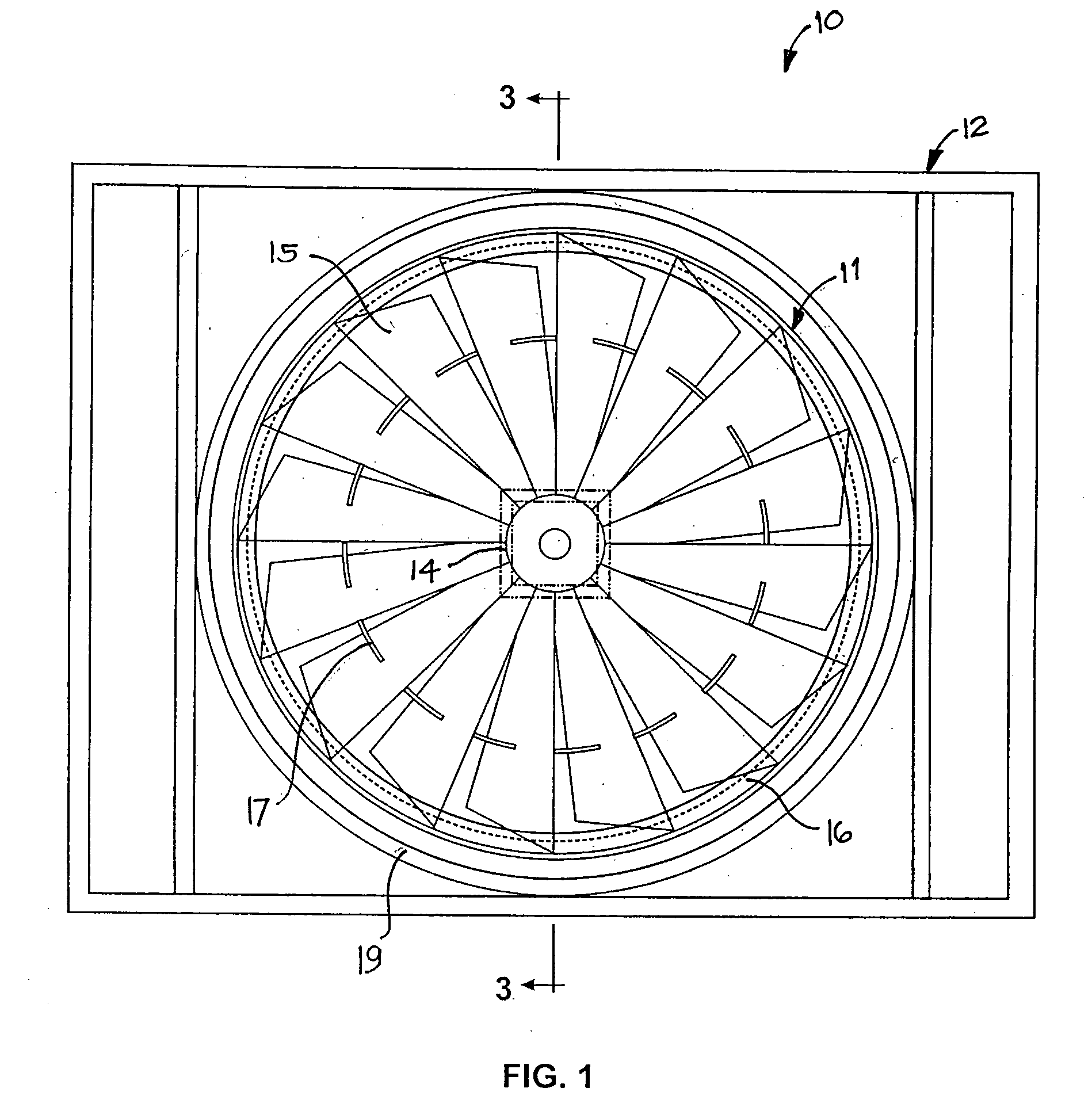
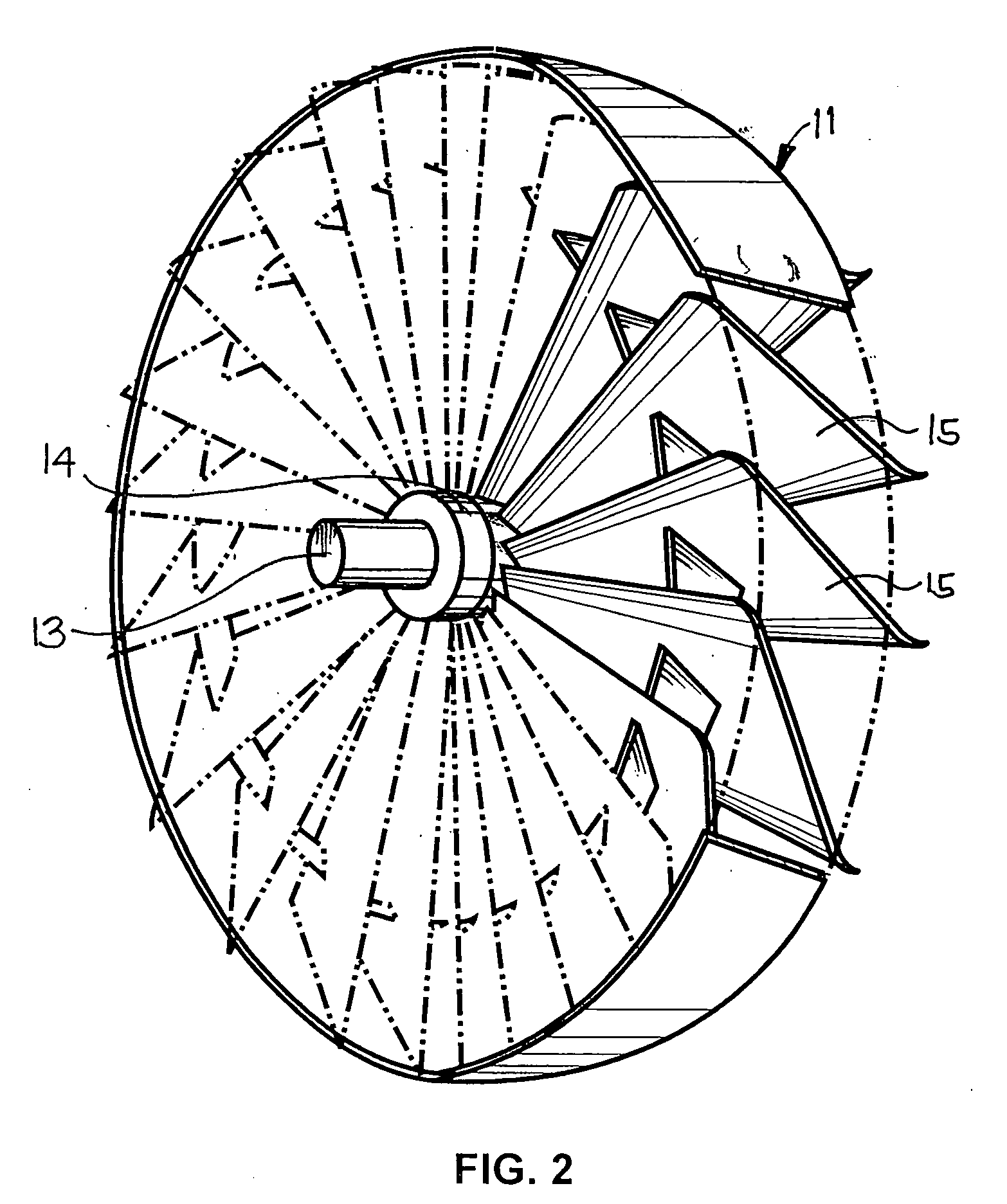
[0014]Referring to the drawings, there is shown a turbine assembly generally designated as 10 comprising a turbine member 11 rotatably mounted on cage member 12 through shafting 13 provided thereof. Said turbine member consisting of a hub 14 having a plurality of blade members 15 being held thereof. Each of the blade member having predetermined length and preferably trapezoidal in shape. Said blade member having cross-section being defined by a flattened central section with its upper surfaces descending gradually towards one end and its inner surfaces descending gradually towards the other end. Each of the blade member may be in the form of a framed structure wherein the outer cover is made of non-corrosive light steel material and the frame made of non-corrosive steel material that includes manganese steel or high carbon steel material. Each of the blade members having an inclination angle of about 45 degrees for purposes of dual reaction or function and for a maximum “flood” and ...


PUM


Abstract

The ‘hydrokinetic turbine assembly’ is a device for the conversion of the kinetic energy of oscillating tidal currents into rotary torque to generate clean electric power. This device is a horizontal axis hydroturbine with a plurality of trapezoidal symmetrical blades placed at about 45 degrees to the axis. The inclination of the blades assures its maximum energy conversion capacity and the dual reaction function of the turbine where ‘floods and ebbs” are alternatively converted into rotary torque. The inner blade frame, its aerodynamic contour, and at least one connective circumferential blade-ring, add strength buoyancy and sensitivity to slow currents. This hydrokinetic turbine is separated from the electric generators and can be placed in pre-planned current flow locations for greater efficiency.

Description

TECHNICAL FIELD[0001]The present invention relates generally to a device for generating energy and more particularly to a hydrokinetic turbine assembly.BACKGROUND OF THE INVENTION[0002]The balancing of ocean water levels causes powerful tidal currents which can serve as a free energy source in attaining renewable electric power. Numerous methods and devices have already been tested and utilized for harnessing and converting the mechanical (kinetic) energy of oceans into useful electric power, however, their practical implementation had encountered numerous problems on account of its economic and environmental nature.[0003]One of the aforementioned devices is the reaction hydraulic turbine for converting the energy of a flow stream. This turbine is positioned in a manner wherein the lower section of the runner is submerged in water so that it can be rotated by the energy of a flowing stream in the same direction as the stream. The operational efficiency of this turbine may be improve...

Claims


Application Information

Patent Timeline
IPC IPC(8): F03B11/02F03B3/12
CPCY02E10/28F03B13/264Y02E10/30Y02E10/20
Inventor PRIORESCHI, ROGER CARRARO
Owner ASIA POWER DEV FOUND
Learn More