[0005]One
advantage of the invention is that enables control action by an engine controller or the like so as to reduce cylinder torque imbalance. The invention, in a preferred embodiment, takes
advantage of the fact that engine speed derivative data (e.g.,
crankshaft speed or acceleration fluctuation data), used in the invention, is already available in most
internal combustion engine systems by virtue of the need to detect misfire, as described in the Background. A method for operating a multi-cylinder
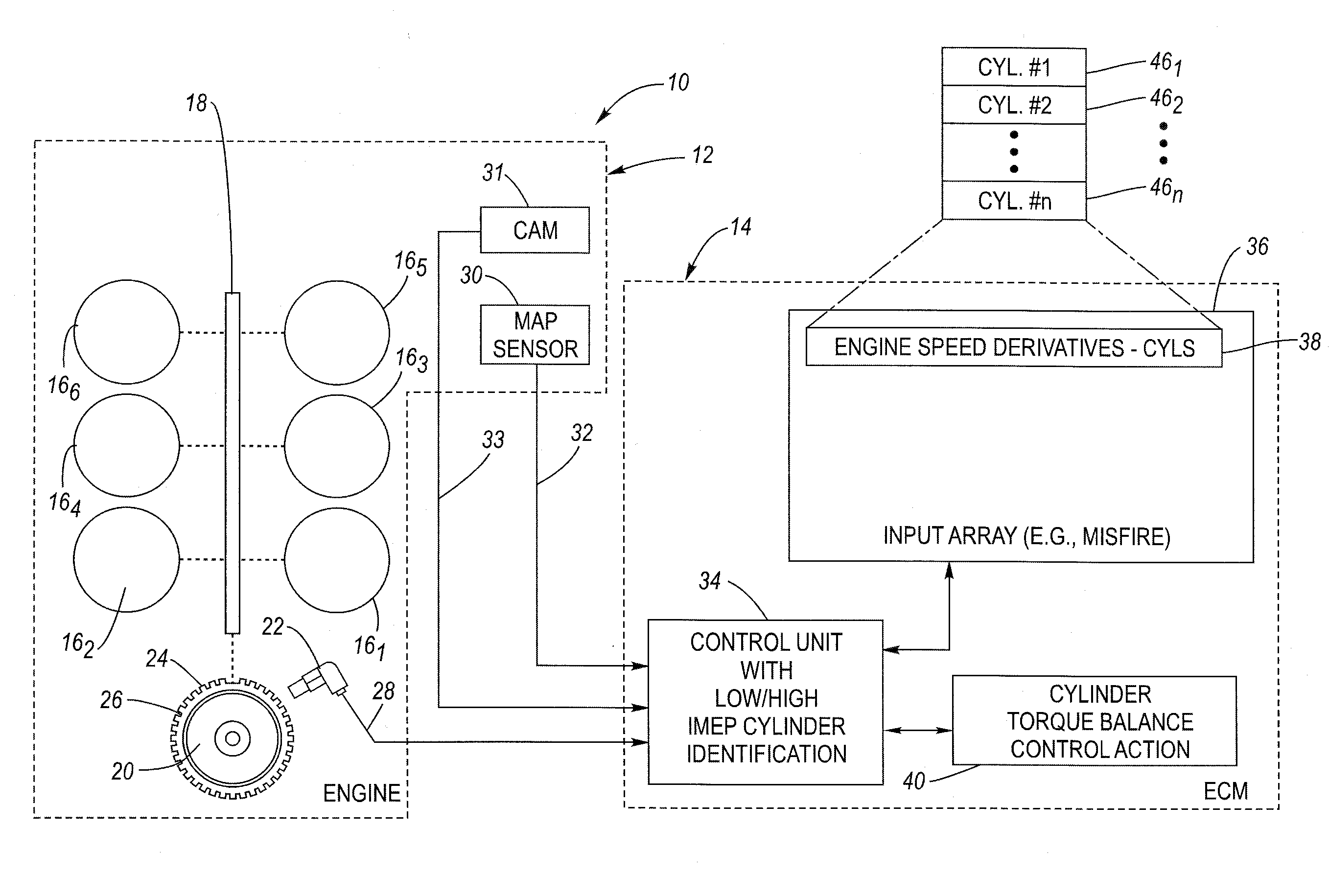
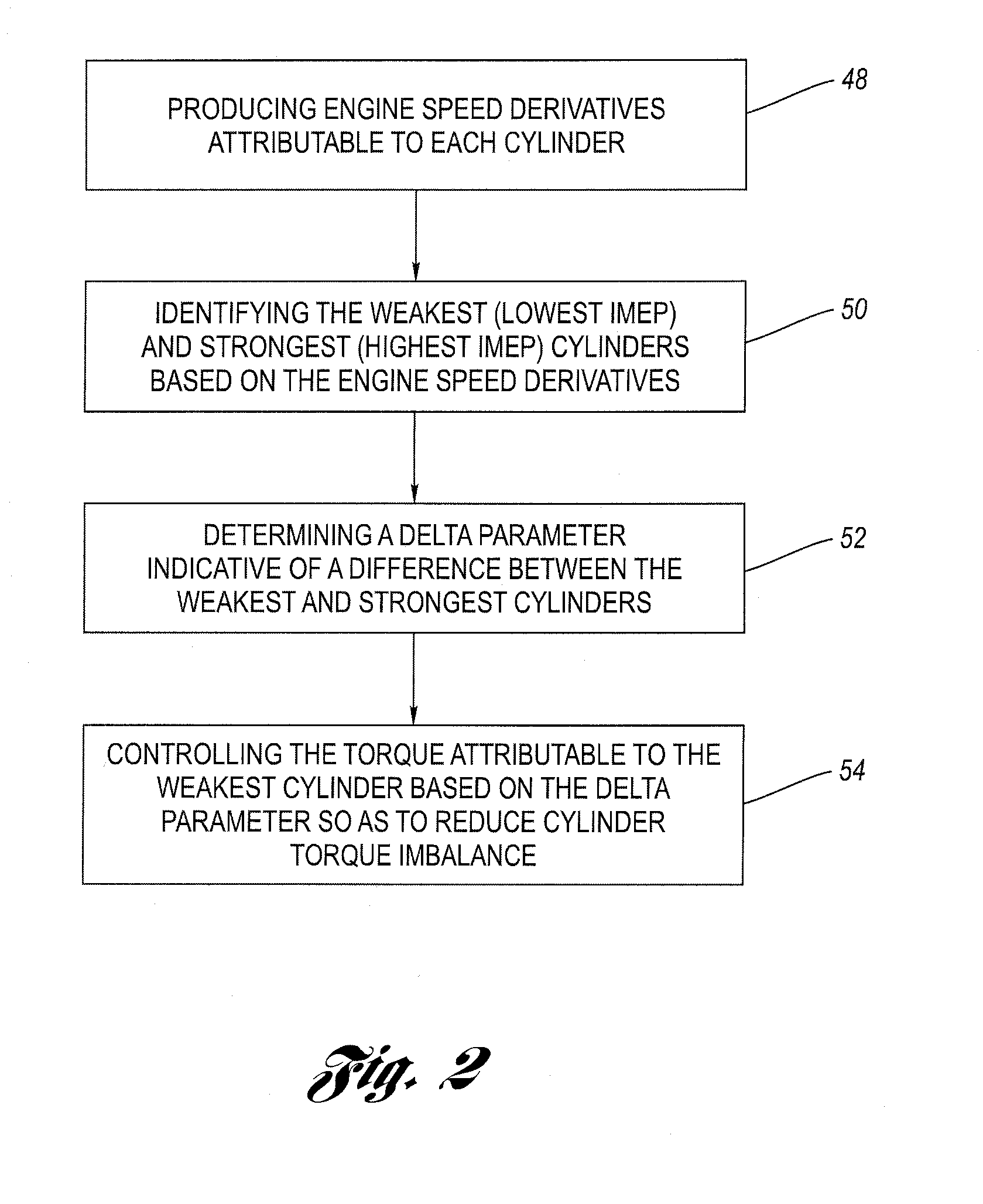
internal combustion engine system includes a number of steps. The first step involves providing an input array including an engine speed derivative for each cylinder of the engine. As used herein, engine speed derivative simply means a value derived from engine speed indicative data, and is not meant to be limited to only the first order mathematical derivative of engine speed (i.e., acceleration), although the term engine speed derivative includes this meaning. Engine speed derivative thus also includes not only the second order mathematical derivative (i.e., jerk acceleration), but also could include still higher order mathematical derivatives as well, as well as other parameter values derived from engine speed data. Next, identifying (i) a first one of the cylinders that has the lowest Indicated Mean Effect Pressure (IMEP) (“weakest” cylinder), and (ii) a second one of the cylinders that has the highest IMEP (“strongest” cylinder), all based on the information in the input array. The next step involves determining a
delta parameter indicative of a difference between the engine speed derivative values for the first and second cylinders. This is significant since the “strongest” cylinder usually follows the “weakest” cylinder in the
firing order, since, by comparison to a “weak” cylinder, the
recovery back to “normal” is perceived as decisive acceleration, thus, even a normal cylinder will be perceived as strong. This is referred to herein as the
shadow effect. The final step involves, in a preferred embodiment, controlling the torque of the first, lowest IMEP (“weakest”) cylinder based on the delta parameter so as to reduce the difference between the weakest and strongest cylinders. In a further, preferred embodiment, the control action is continued until it is no longer the “weakest” cylinder. Then, any remaining “weak” cylinders are adjusted through control action. The “weak” cylinders are preferably adjusted first because a weak cylinder creates the
perception of exceptionally good performance for the cylinder which follows in the
firing order as noted above. Preferably, the
crankshaft positions are corrected for tooth
machining errors before calculating the engine speed derivatives. Other features, aspects and advantages will become apparent in light of the description to follow.
is that enables control action by an engine controller or the like so as to reduce cylinder torque imbalance. The invention, in a preferred embodiment, takes
advantage of the fact that engine speed derivative data (e.g.,
crankshaft speed or acceleration fluctuation data), used in the invention, is already available in most internal combustion engine systems by virtue of the need to detect misfire, as described in the Background. A method for operating a multi-cylinder internal combustion engine system includes a number of steps. The first step involves providing an input array including an engine speed derivative for each cylinder of the engine. As used herein, engine speed derivative simply means a value derived from engine speed indicative data, and is not meant to be limited to only the first order mathematical derivative of engine speed (i.e., acceleration), although the term engine speed derivative includes this meaning. Engine speed derivative thus also includes not only the second order mathematical derivative (i.e., jerk acceleration), but also could include still higher order mathematical derivatives as well, as well as other parameter values derived from engine speed data. Next, identifying (i) a first one of the cylinders that has the lowest Indicated Mean Effect Pressure (IMEP) (“weakest” cylinder), and (ii) a second one of the cylinders that has the highest IMEP (“strongest” cylinder), all based on the information in the input array. The next step involves determining a delta parameter indicative of a difference between the engine speed derivative values for the first and second cylinders. This is significant since the “strongest” cylinder usually follows the “weakest” cylinder in the
firing order, since, by comparison to a “weak” cylinder, the
recovery back to “normal” is perceived as decisive acceleration, thus, even a normal cylinder will be perceived as strong. This is referred to herein as the
shadow effect. The final step involves, in a preferred embodiment, controlling the torque of the first, lowest IMEP (“weakest”) cylinder based on the delta parameter so as to reduce the difference between the weakest and strongest cylinders. In a further, preferred embodiment, the control action is continued until it is no longer the “weakest” cylinder. Then, any remaining “weak” cylinders are adjusted through control action. The “weak” cylinders are preferably adjusted first because a weak cylinder creates the
perception of exceptionally good performance for the cylinder which follows in the firing order as noted above. Preferably, the crankshaft positions are corrected for tooth
machining errors before calculating the engine speed derivatives. Other features, aspects and advantages will become apparent in light of the description to follow.


