Method for low and high IMEP cylinder identification for cylinder balancing

a technology of cylinder balancing and identification, applied in the direction of electrical control, process and machine control, instruments, etc., can solve the problem of uncombusted fuel entering the exhaust system, and achieve the effect of reducing the imbalance of cylinder torque and good performan

Active Publication Date: 2010-03-16
DELPHI TECH IP LTD
View PDF2 Cites 5 Cited by
  • Summary
  • Abstract
  • Description
  • Claims
  • Application Information

AI Technical Summary

Benefits of technology

[0005]One advantage of the invention is that enables control action by an engine controller or the like so as to reduce cylinder torque imbalance. The invention, in a preferred embodiment, takes advantage of the fact that engine speed derivative data (e.g., crankshaft speed or acceleration fluctuation data), used in the invention, is already available in most internal combustion engine systems by virtue of the need to detect misfire, as described in the Background. A method for operating a multi-cylinder internal combustion engine system includes a number of steps. The first step involves providing an input array including an engine speed derivative for each cylinder of the engine. As used herein, engine speed derivative simply means a value derived from engine speed indicative data, and is not meant to be limited to only the first order mathematical derivative of engine speed (i.e., acceleration), although the term engine speed derivative includes this meaning. Engine speed derivative thus also includes not only the second order mathematical derivative (i.e., jerk acceleration), but also could include still higher order mathematical derivatives as well, as well as other parameter values derived from engine speed data. Next, identifying (i) a first one of the cylinders that has the lowest Indicated Mean Effect Pressure (IMEP) (“weakest” cylinder), and (ii) a second one of the cylinders that has the highest IMEP (“strongest” cylinder), all based on the information in the input array. The next step involves determining a delta parameter indicative of a difference between the engine speed derivative values for the first and second cylinders. This is significant since the “strongest” cylinder usually follows the “weakest” cylinder in the firing order, since, by comparison to a “weak” cylinder, the recovery back to “normal” is perceived as decisive acceleration, thus, even a normal cylinder will be perceived as strong. This is referred to herein as the shadow effect. The final step involves, in a preferred embodiment, controlling the torque of the first, lowest IMEP (“weakest”) cylinder based on the delta parameter so as to reduce the difference between the weakest and strongest cylinders. In a further, preferred embodiment, the control action is continued until it is no longer the “weakest” cylinder. Then, any remaining “weak” cylinders are adjusted through control action. The “weak” cylinders are preferably adjusted first because a weak cylinder creates the perception of exceptionally good performance for the cylinder which follows in the firing order as noted above. Preferably, the crankshaft positions are corrected for tooth machining errors before calculating the engine speed derivatives. Other features, aspects and advantages will become apparent in light of the description to follow.
is that enables control action by an engine controller or the like so as to reduce cylinder torque imbalance. The invention, in a preferred embodiment, takes advantage of the fact that engine speed derivative data (e.g., crankshaft speed or acceleration fluctuation data), used in the invention, is already available in most internal combustion engine systems by virtue of the need to detect misfire, as described in the Background. A method for operating a multi-cylinder internal combustion engine system includes a number of steps. The first step involves providing an input array including an engine speed derivative for each cylinder of the engine. As used herein, engine speed derivative simply means a value derived from engine speed indicative data, and is not meant to be limited to only the first order mathematical derivative of engine speed (i.e., acceleration), although the term engine speed derivative includes this meaning. Engine speed derivative thus also includes not only the second order mathematical derivative (i.e., jerk acceleration), but also could include still higher order mathematical derivatives as well, as well as other parameter values derived from engine speed data. Next, identifying (i) a first one of the cylinders that has the lowest Indicated Mean Effect Pressure (IMEP) (“weakest” cylinder), and (ii) a second one of the cylinders that has the highest IMEP (“strongest” cylinder), all based on the information in the input array. The next step involves determining a delta parameter indicative of a difference between the engine speed derivative values for the first and second cylinders. This is significant since the “strongest” cylinder usually follows the “weakest” cylinder in the firing order, since, by comparison to a “weak” cylinder, the recovery back to “normal” is perceived as decisive acceleration, thus, even a normal cylinder will be perceived as strong. This is referred to herein as the shadow effect. The final step involves, in a preferred embodiment, controlling the torque of the first, lowest IMEP (“weakest”) cylinder based on the delta parameter so as to reduce the difference between the weakest and strongest cylinders. In a further, preferred embodiment, the control action is continued until it is no longer the “weakest” cylinder. Then, any remaining “weak” cylinders are adjusted through control action. The “weak” cylinders are preferably adjusted first because a weak cylinder creates the perception of exceptionally good performance for the cylinder which follows in the firing order as noted above. Preferably, the crankshaft positions are corrected for tooth machining errors before calculating the engine speed derivatives. Other features, aspects and advantages will become apparent in light of the description to follow.

Problems solved by technology

Additionally, un-combusted fuel enters the exhaust system, which is undesirable.

Method used


Image

  • Method for low and high IMEP cylinder identification for cylinder balancing
  • Method for low and high IMEP cylinder identification for cylinder balancing
  • Method for low and high IMEP cylinder identification for cylinder balancing

Examples


Embodiment Construction

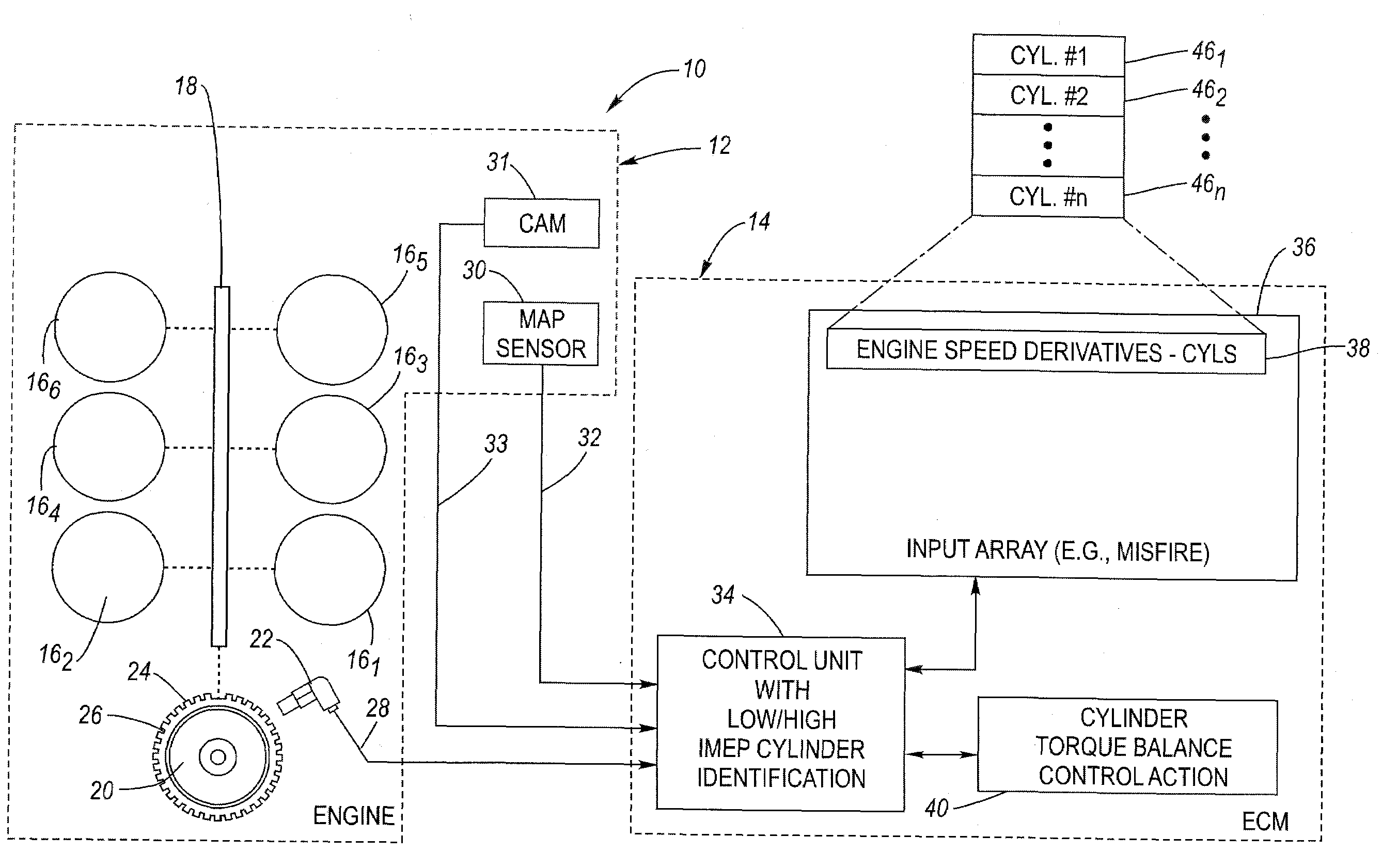
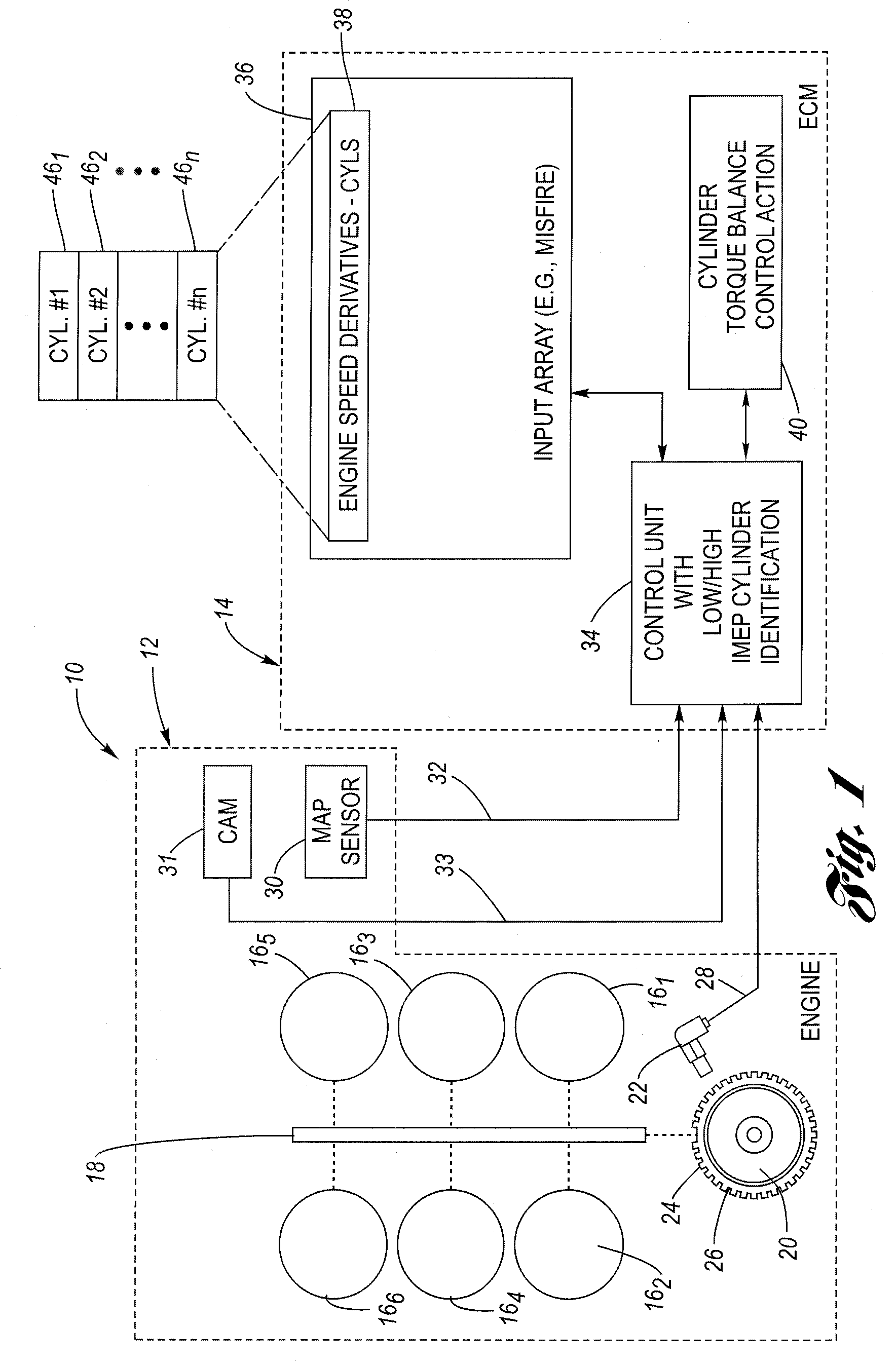
[0011]Referring now to the drawings wherein like reference numerals are used to identify identical components in the various views, FIG. 1 shows an internal combustion engine system 10 including an internal combustion engine 12 whose operation is controlled by a programmed, electronic engine control module (ECM) 14 or the like. System 10 is configured, in one embodiment, to already have available real-time engine speed derivative data by virtue of also having misfire detection capability, as known in the art. Of course, misfire detection capability is not required for purposes of the present invention.

[0012]The engine 12 includes a plurality of cylinders, illustrated in exemplary fashion as a V-type, six (6) cylinder engine where the cylinders are designated 161, 162, 163, . . . 166. In one arrangement, for example, the firing order may be designated as cylinders numbers 2-3-4-5-6-1. Of course, other numbering schemes and / or firing orders are possible. Moreover, the present inventio...


PUM


Abstract

A system and method for identifying the cylinders having the lowest (“weakest”) and highest (“strongest”) Indicated Mean Effective Pressure (IMEP) utilizes engine speed derivative and / or higher order derivative values typically available in an engine control module by virtue of the need to detect misfire. A delta parameter is calculated that is indicative of the difference between the engine speed derivatives and / or higher order derivatives for the “weakest” and the “strongest” cylinders. Control action is then taken to balance the cylinders, based on the delta parameter, by first increasing torque for the “weakest” cylinder, by at least one increasing spark advance, increasing fuel, decreasing dilution (EGR) or slowing decay of fuel control on cold start. Once the weakest cylinder has been balanced, the control action is then directed to increasing torque of the new “weakest” cylinder.

Description

TECHNICAL FIELD[0001]The present invention relates generally to a method for low and high indicated mean effective pressure (IMEP) cylinder identification to enable fuel / spark or other control for cylinder balancing.BACKGROUND OF THE INVENTION[0002]A misfire condition in an internal combustion engine results from either a lack of combustion of the air / fuel mixture, sometimes called a total misfire, or an instability during combustion, sometimes referred to as a partial misfire. In such case, torque production attributable to the misfiring cylinder decreases, due to, among other things, a reduced level of combustion (i.e., manifested by a reduced Indicated Mean Effective Pressure (IMEP)). Additionally, un-combusted fuel enters the exhaust system, which is undesirable. Because of the possible impact on the ability to meet certain emission requirements, engine misfire detection is routinely provided on automotive vehicles. Most common approaches use various engine speed derivatives (e....

Claims


Application Information

Patent Timeline
Patent Type & Authority Patents(United States)
IPC IPC(8): F02D45/00G06F19/00
CPCF02D41/0085
Inventor MCKAY, DANIEL L.MALACZYNSKI, GERARD W.TITUS, JOSHUA J.
Owner DELPHI TECH IP LTD
Why Eureka
Try Eureka