Partially Self-Refueling Zero Emissions System

a self-refueling, zero-emission technology, applied in the direction of machines/engines, reciprocating combination engines, electric generator control, etc., can solve the problem that countries face the threat of direct energy terrorism, different countries have experienced interruptions in the availability of fossil fuel supplies, and cut off access to any non-domestic source of oil supplies without warning

Active Publication Date: 2009-10-22
MORIARTY DONALD E
View PDF80 Cites 56 Cited by
  • Summary
  • Abstract
  • Description
  • Claims
  • Application Information

AI Technical Summary

Benefits of technology

[0014]In light of the problems and deficiencies inherent in the prior art, the present invention seeks to overcome these by providing a method and device to optimize the cumulative beneficial effect of harvesting all available forms of lost energy, including energy that is lost while a vehicle is in motion (e.g., kinetic, inertia, friction, theromodynamic, and aerodynamic losses). The cumulative energy that is recovered is converted t

Problems solved by technology

Over the past few decades different countries have experienced interruptions in the availability of fossil fuel supplies due to an external oil embargo and domestic natural disasters.
In addition, countries face the lingering threat of direct energy terrorism targeted at our petroleum refineries and related infrastructure.
Indirect threats also exist in the form of political/terrorist blackmail which may cut off access to any non-domestic source of oil supplies without warning.
Obviously, such a scenario doesn't take into account the probability of fuel rationing nor the petroleum output of Canada and Mexico.
Finally, some studies suggest that within 10 to 15 years the worldwide supply of crude oil deposits may be reaching the point of peak production, known as the Hubbert Point, after which supplies will steadily diminish followed by an ever-increasing cost to the consumer.
The rise of crude oil prices from early 2008 to September 2008 proved to be burdensome for businesses and consumers worldwide.
However, it has been suggested that a major drawback with increasing the number of electric and hybrid-electric vehicles in use is the large quantities of batteries to power the electric motors and other electrical devices.
If improperly charged, batteries can be permanently damaged.
Additionally, if left uncharged for long periods of time, the batteries can sulfate or become unusable.
Moreover, battery storage is heavy,

Method used


Image

  • Partially Self-Refueling Zero Emissions System
  • Partially Self-Refueling Zero Emissions System
  • Partially Self-Refueling Zero Emissions System

Examples


Embodiment Construction

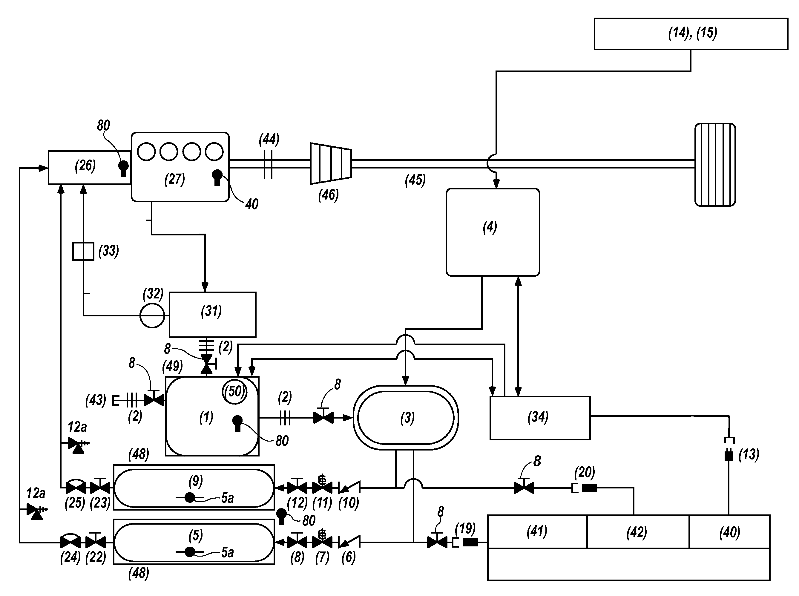
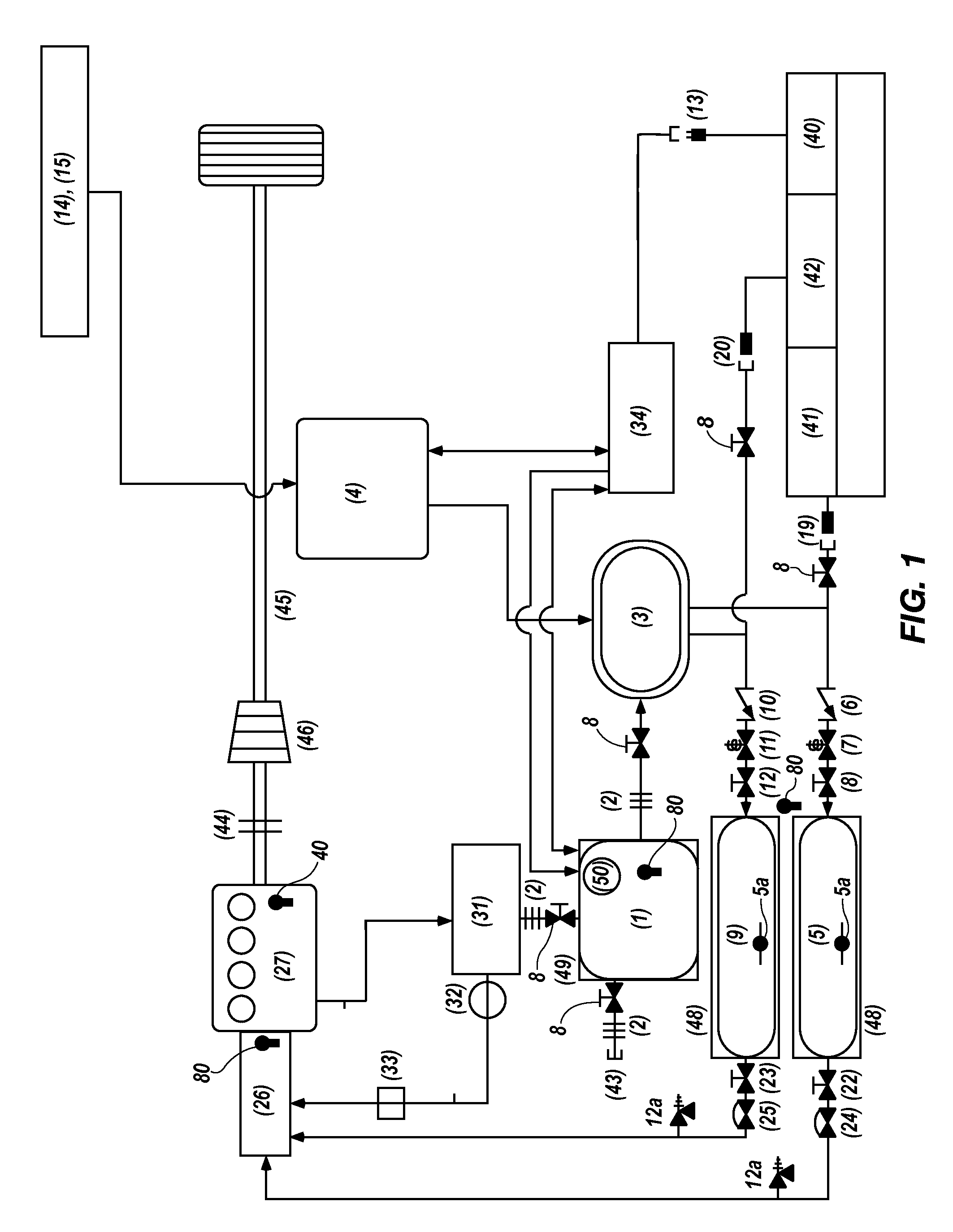
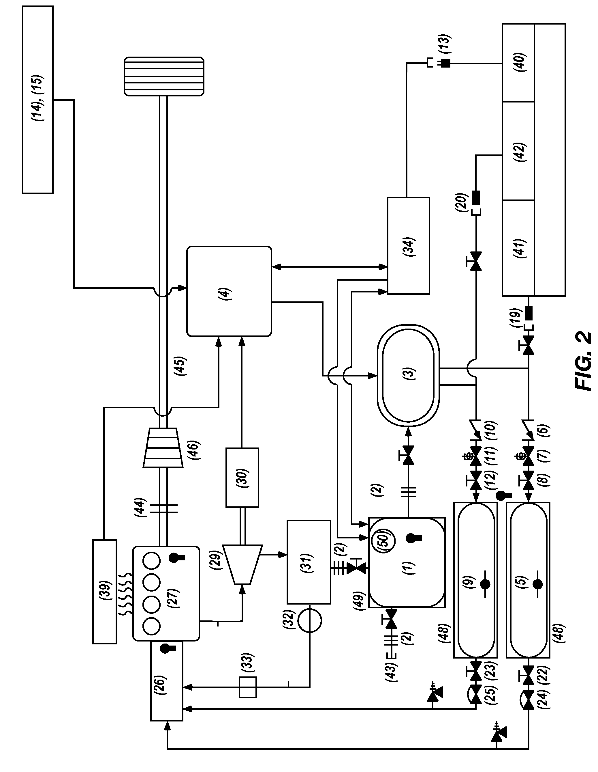
[0033]The following description of exemplary embodiments of the invention makes reference to the accompanying drawings, which form a part hereof and in which are shown, by way of illustration, exemplary embodiments in which the invention may be practiced. While these exemplary embodiments are described in sufficient detail to enable those skilled in the art to practice the invention, it should be understood that other embodiments may be realized and that various changes to the invention may be made without departing from the spirit and scope of the present invention. Thus, the following more detailed description of the embodiments of the present invention is not intended to limit the scope of the invention, as claimed, but is presented for purposes of illustration only and not limitation to describe the features and characteristics of the present invention, to set forth the best mode of operation of the invention, and to sufficiently enable one skilled in the art to practice the inv...


PUM


Abstract

A method and device to optimize the cumulative beneficial effect of harvesting all available forms of lost energy, including energy that is lost while a vehicle is in motion (e.g., kinetic, inertia, friction, thermodynamic, and aerodynamic losses). The cumulative energy that is recovered is converted to electrical energy which powers the on-board electrolyzer to produce more hydrogen and oxygen while the system is in operation and stationary. Stationary, passive means of energy, solar, wind, hydro, etc. will also be available to power the electrolyzer. The system also contemplates utilizing passive means of energy to power a non-mobile system which incorporates an internal or external combustion engine in place of a fuel cell.

Description

PRIORITY[0001]This application claims priority to U.S. Provisional Patent Application No. 61 / 124,469 filed Apr. 16, 2008 and is incorporated herein by reference in its entirety.FIELD OF INVENTION[0002]The present invention relates to clean air engine systems, more particularly to clean air engine systems using water by electrolysis to generate the gases to fuel an internal or external engine, fuel cell or other device.BACKGROUND OF THE INVENTION[0003]Global warming has mandated a multitude of domestic federal and state regulations and international treaties all designed to limit the harmful effects related to the combustion of fossil fuels. These regulations generally target CO2 emissions, which have been acknowledged by some as contributing to atmospheric greenhouse heating.[0004]Over the past few decades different countries have experienced interruptions in the availability of fossil fuel supplies due to an external oil embargo and domestic natural disasters. In addition, countrie...

Claims


Application Information

Patent Timeline
IPC IPC(8): F02B73/00F02B43/08F03D9/00H02K21/16H02K7/10H02N2/18F02D29/06F03G7/08
CPCF03G6/001F01K23/10Y02E10/46
Inventor MORIARTY, DONALD
Owner MORIARTY DONALD E
Why Eureka
Try Eureka