
System for loading collars onto bolts in large-scale manufacturing operations

a technology for bolts and collars, applied in the direction of manufacturing tools, metal-working feeding devices, shaping tools, etc., can solve the problems of preventing a good, accurate loading of collars, loss of operation time,

Active Publication Date: 2009-10-22
ELECTROIMPACT
View PDF1 Cites 40 Cited by
  • Summary
  • Abstract
  • Description
  • Claims
  • Application Information

AI Technical Summary

Benefits of technology

[0007]Accordingly, there is shown and described herein a gripperless system for conveying collars having a center opening to a position where an axis of the center opening of the collar is alignable with a centerline axis of a swaging die tool for bolts, the swaging die tool being part of a tool assembly for manufacturing operations, comprising: a collar feed assembly, including a feed channel therein through which a collar is conveyed by compressed air, the feed channel being generally perpendicular to the swaging die tool centerline axis as the feed channel approaches the swaging die tool, wherein the feed assembly includes a stop assembly for the collar, the collar being operatively positioned, solely by action of the compressed air, relative to the swaging die tool centerline axis, wherein there is sufficient clearance between the collar and the channel to permit movement of the collar as a forward end of a die pin portion of the die tool engages the center opening of the collar, resulting in accurate loading of the collar onto the die pin. wherein the feed assembly or the swaging die tool are movable sufficiently thereafter to permit a die pin-engaged collar to be moved forward for engagement with a tail end of a bolt.

Problems solved by technology

The tight clearance between the die pin and the internal diameter (ID) of the collar often results in problems in the collar transfer operation.
Transfer of the collar from the feed tube to the finger assembly can result in the collar being gripped by the gripper fingers off-axis, cocked in the gripper fingers, or otherwise misaligned, preventing a good, accurate loading of the collar onto the die pin.
Such misaligned collars result in loss of operation time. difficulties in swaging and poor fastening operations.
Detection and removal of such misaligned collars is time consuming, expensive and requires cleanup.
The tight clearance between the collar ID and the bolt often results in further problems as the collar is transferred onto the bolt.
Transfer of the collar from the die pin to the bolt tail can result in the collar becoming cocked on the bolt or otherwise misaligned.
Misaligned collars oil the bolt also result in loss of operation time, difficulties in swaging and poor fastening operations.

Method used


Image

  • System for loading collars onto bolts in large-scale manufacturing operations
  • System for loading collars onto bolts in large-scale manufacturing operations
  • System for loading collars onto bolts in large-scale manufacturing operations

Examples


Embodiment Construction

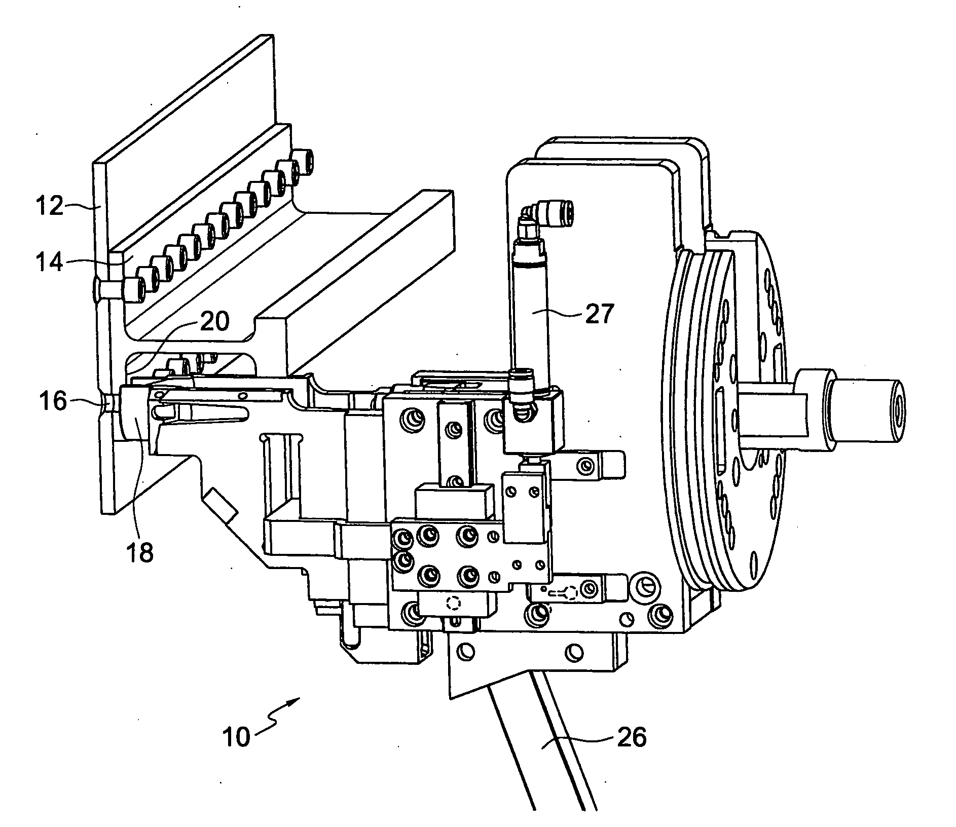
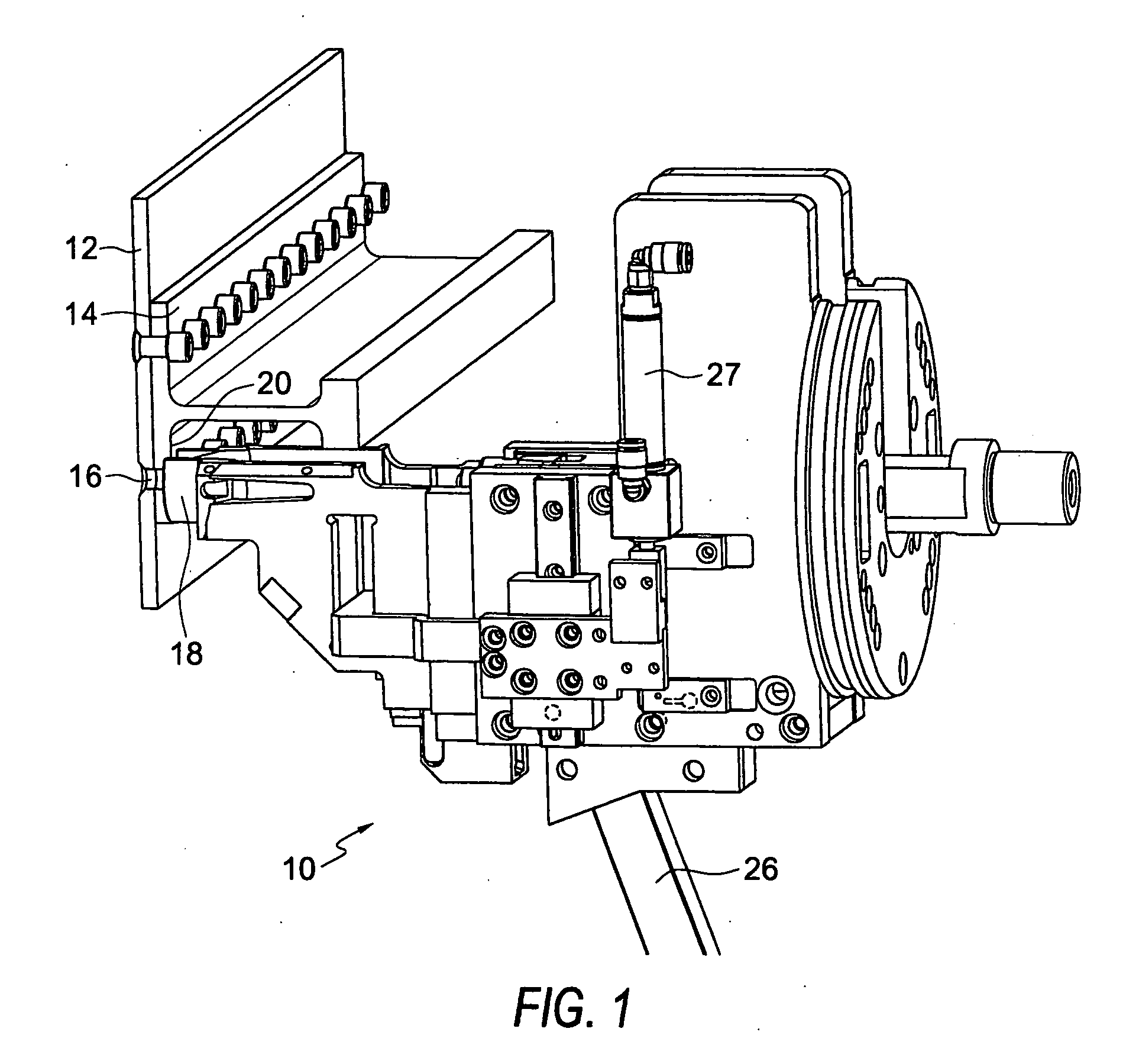
[0018]FIG. 1 shows a portion 10 of a tool assembly for fastening two workpiece parts, referred to as a stackup, together by means of a through-bolt and a collar swaged onto a tail end of the bolt, which is moved through an opening in the stackup into the collar prior to swaging. In the embodiment shown, the stackup is a portion of an aircraft wing, e.g. a panel 12 and a stringer 14. Such a combination, however, is for illustration and is only one example of two or more workpiece combinations which can be fastened using the bolt and collar fastener assembly system shown and described herein.

[0019]FIG. 1 shows an opening 16 in the stackup which has been already drilled by a drilling tool (not shown) portion of the tool assembly, the drilling tool being located on the opposite side of the stackup from tool assembly portion 10. FIG. 1 shows tool assembly portion 10 in a “clamped up” position, with a clamping foot 18 positioned against one surface 20 of stringer 14.

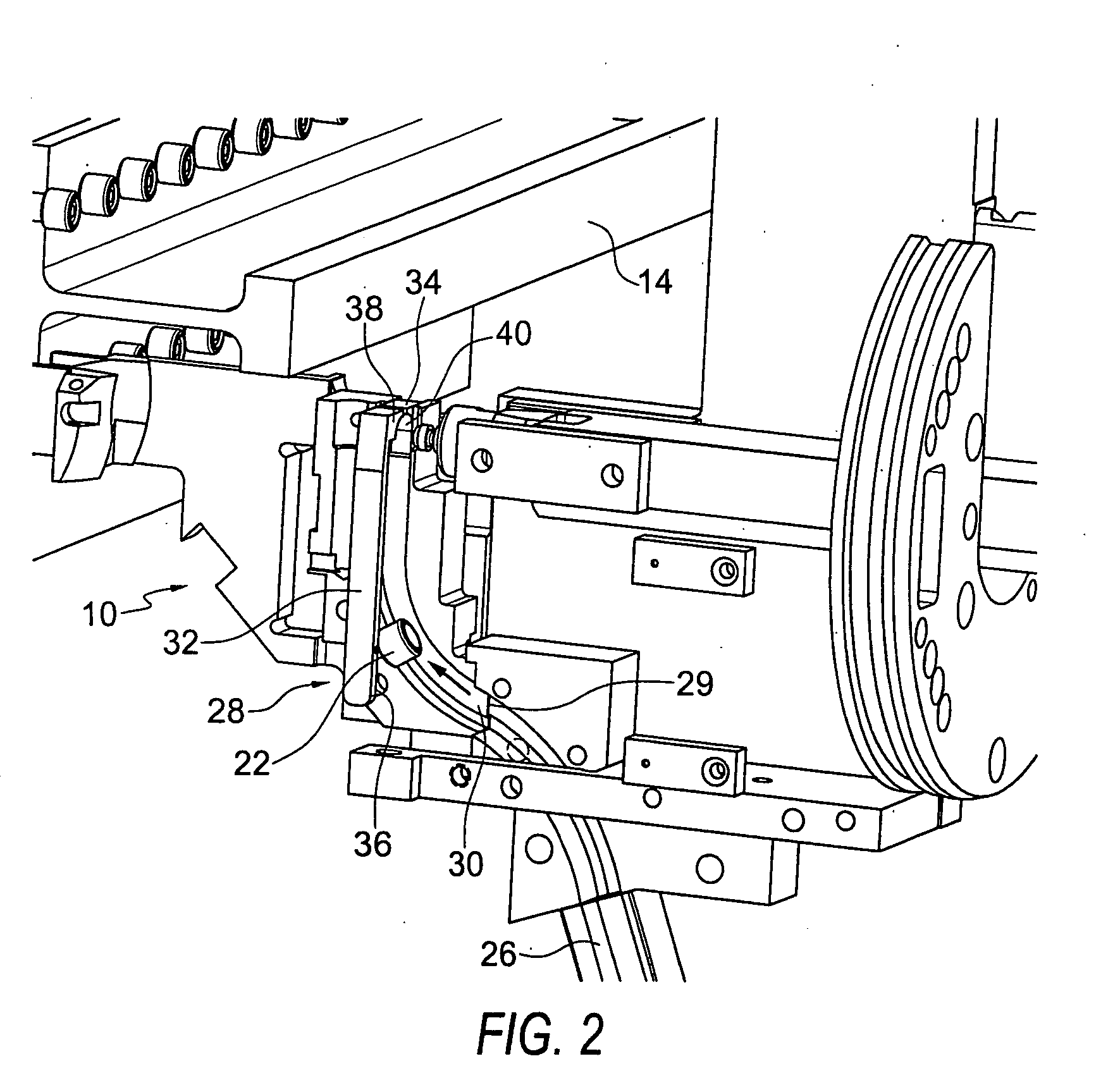
[0020]FIG. 2 shows the...


PUM

PropertyMeasurementUnit
Lengthaaaaaaaaaa
Sizeaaaaaaaaaa
Flexibilityaaaaaaaaaa

Abstract

The system includes a moving feed assembly through which a collar is moved by compressed air to a position in substantial alignment with the centerline of a swaging die assembly. Two spring-loaded fingers are mounted on opposing sides of the feed assembly for receiving the collar by compressed air action where it is maintained in substantial alignment with the swaging die assembly. The spring action of the fingers is strong enough that the collar can be pressed firmly against a curved receiving portion of the fingers by the compressed air. A die pin portion of the swaging die is then inserted into the collar, thereafter maintaining the position of the collar as the feed assembly with the opposing fingers are stripped away from the collar, leaving the die pin-engaged collar free to be moved by action of a ram assembly to a stackup of parts to be fastened, where the collar can be transferred onto a bolt which extends through the stackup.

Description

TECHNICAL FIELD[0001]This invention relates generally to assembly systems for large-scale manufacturing operations, such as for fastening together parts of aircraft wings or similar operations, and more specifically concerns a bolt collar transfer system for moving bolt collars into an aligned position with a swaging die tool assembly which then moves the collar to the parts. The collar is then swaged on a bolt extending through the parts.BACKGROUND OF THE INVENTION[0002]Systems for performing fastening operations involving bolts and collars which are swaged on the bolts in the manufacture of large workpiece assemblies such as commercial aircraft wings are known. An example of such a system is shown in U.S. Pat. No. 5,437,094, owned by the assignee of the present invention. Such systems typically involve a tool assembly which moves along the workpiece under computer control, performing fastening operations at successive locations. A drilling tool is used to first drill a hole in the...

Claims


Application Information

Patent Timeline
IPC IPC(8): B21D37/00
CPCB65G51/02Y10T29/49998B21D43/00Y10T29/53717Y10T29/5377B23P2700/01B21J15/32Y10T29/53478B21D43/02B23P19/001B21J15/022Y10T29/53387
Inventor TOMCHICK, SCOTT C.
Owner ELECTROIMPACT
Features
  • Generate Ideas
  • Intellectual Property
  • Life Sciences
  • Materials
  • Tech Scout
  • Unparalleled Data Quality
  • Higher Quality Content
  • 60% Fewer Hallucinations
Learn More