

Process and system for the transfer of a metal catalyst component from one particle to another
- Summary
- Abstract
- Description
- Claims
- Application Information
AI Technical Summary
Benefits of technology
Problems solved by technology
Method used
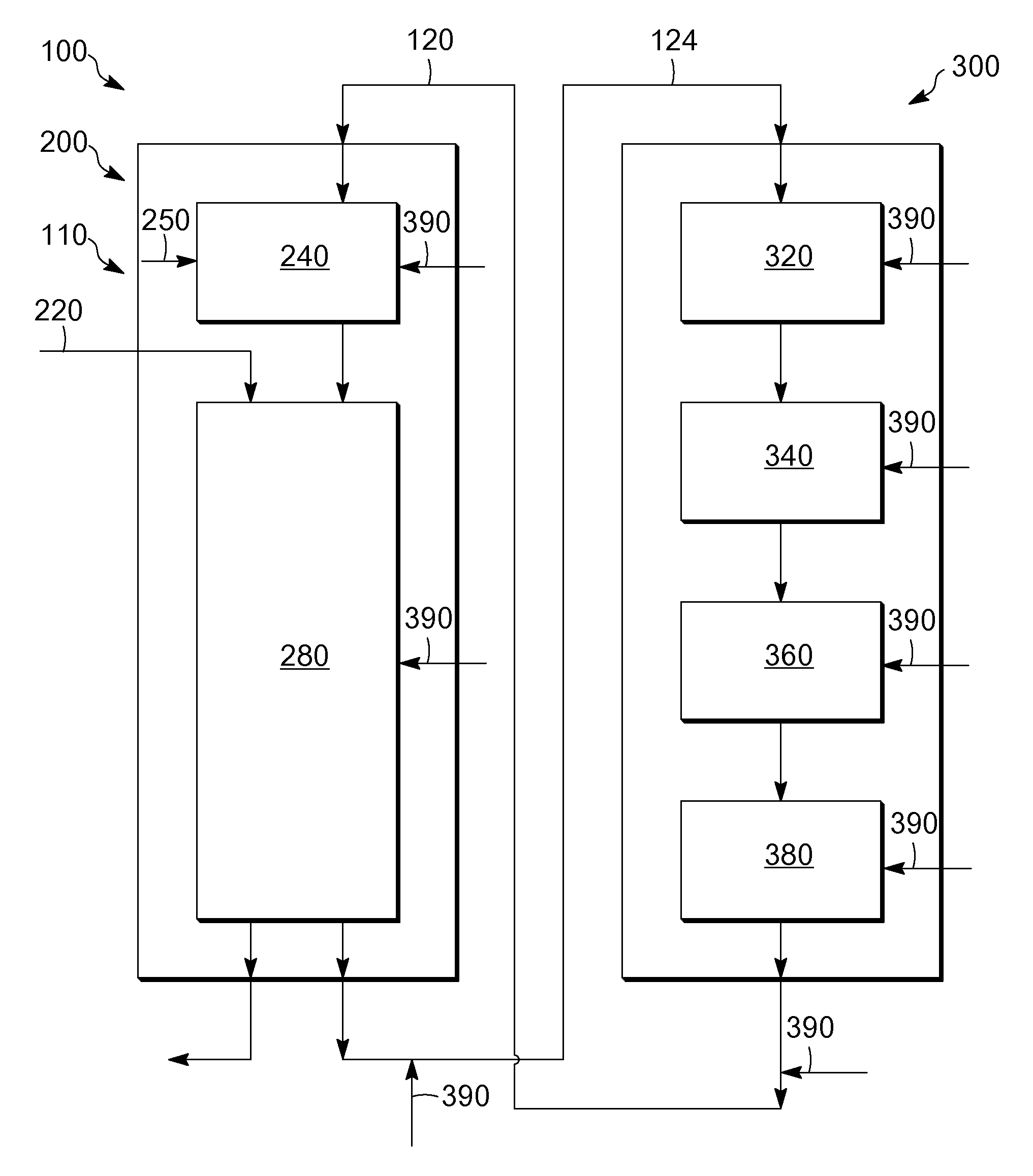
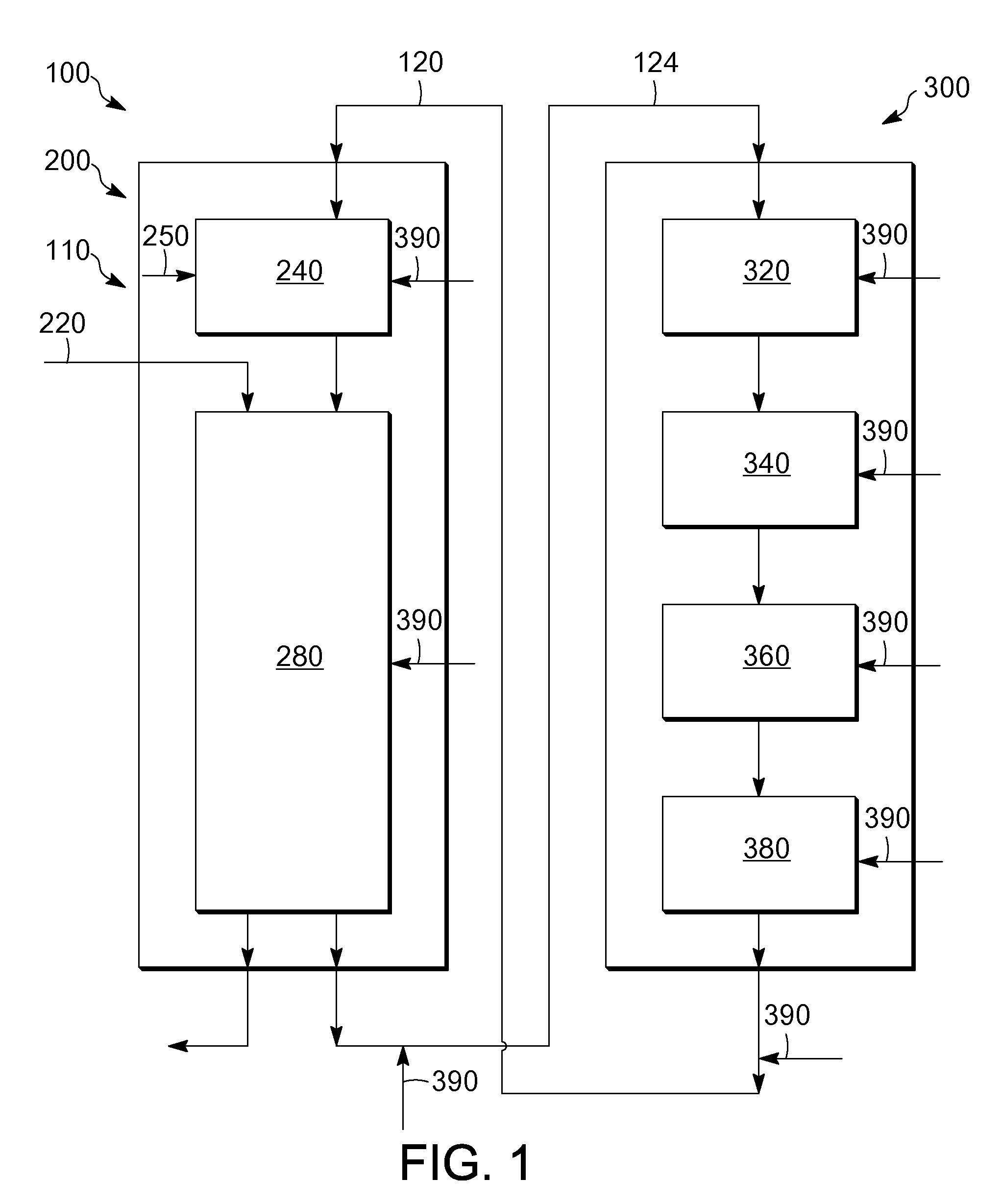
Image

Examples
example 1
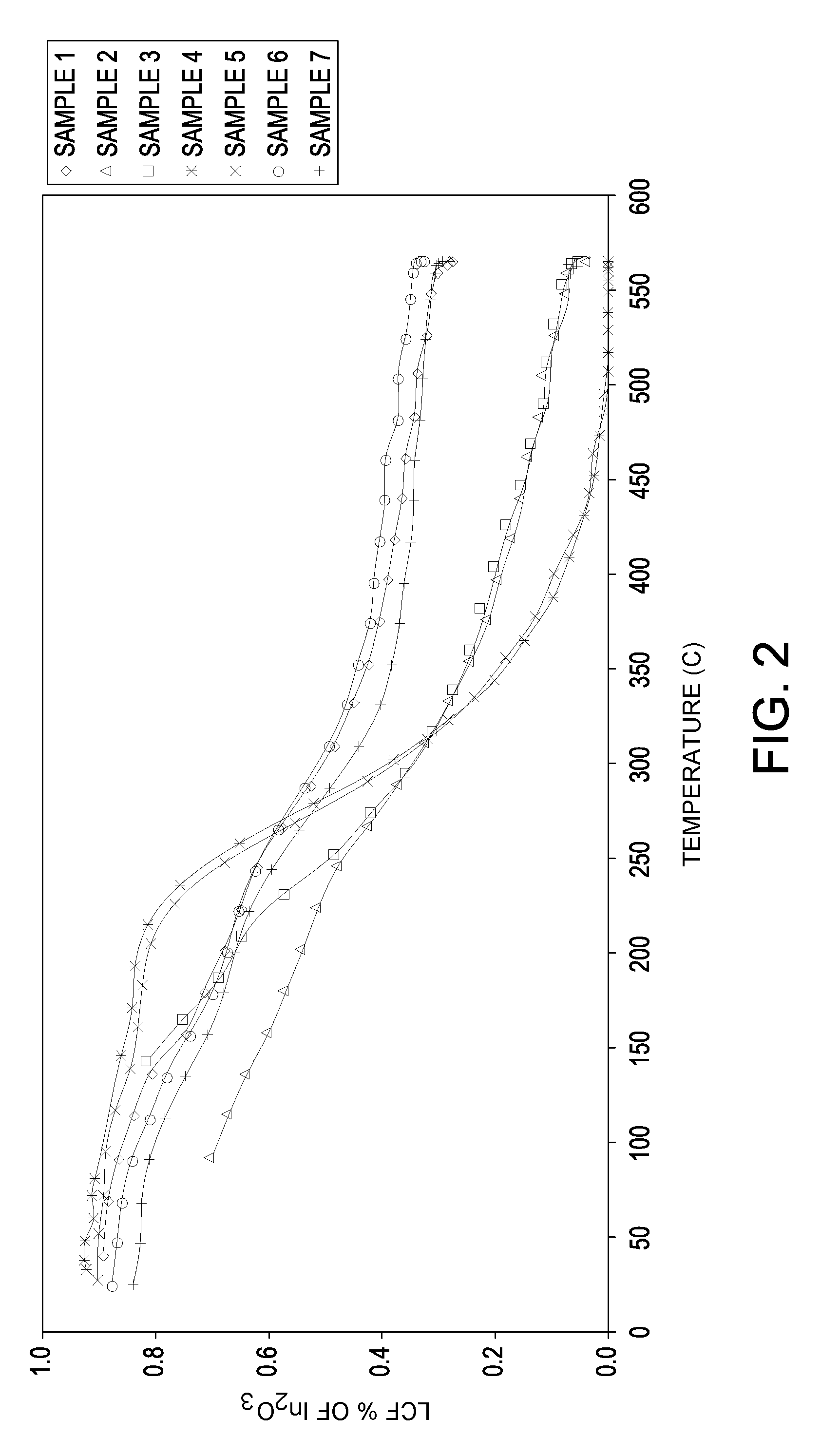
[0067]Seven samples of particles are made with varying orders of impregnation and optionally calcination at a temperature of at least about 750° C. in air (abbreviated “HiT”) on the base or between metal impregnations. Samples 1 and 6 are made with a high temperature calcination of 865° C. between the indium and the platinum impregnations.
[0068]The supports are made by an oil drop method followed by standard heat treatment procedures. Tin is incorporated into the aluminum sol such that the formed support contains about 0.30%, by weight, tin. The support of a Sample 7 is made in similar fashion except that indium chloride solution is added along with a tin-containing solution to the aluminum sol and co-gelled by the oil drop method. The indium is impregnated on the supports from an aqueous solution containing indium chloride or indium nitrate and hydrogen chloride. The platinum is impregnated onto the supports from an aqueous solution of chloroplatinic acid and hydrogen chloride. For...
example 2
[0073]Two catalyst samples are made and tested for loss of indium. The catalysts include supports made by an oil drop method with the tin incorporated into the aluminum sol followed by a standard heat treatment procedure, i.e., a calcination under 750° C. The first sample (Sample 8) is made by impregnating indium onto an alumina support followed by a high temperature calcination (greater than 750° C.) and then followed by a separate platinum impregnation. The second sample (Sample 9) is made by co-impregnating indium and platinum on a gamma alumina support with no intermediate high temperature calcination. After the impregnations, each sample is treated in a similar fashion including oxychlorination and reduction treatments to obtain final chloride levels. The final composition of each sample in weight percent based on the catalyst is depicted in the following table:
TABLE 2Sample 8Sample 9Component(Weight Percent)(Weight Percent)In0.310.32Pt0.300.30Sn0.270.30Cl1.181.06
[0074]The indi...
example 3
[0077]Samples 8 and 9 are exposed again at Condition 4 as depicted in Table 5 for a period of 100 hours. The results after 100 hours along with the Condition 4 results after 10 hours from Example 2 are depicted in the table below:
TABLE 5Sample 8Sample 9Time at(Wt. % Indium Loss(Wt. % Indium LossCondition 4Based on Wt. of Indium)Based on Wt. of Indium) 10 hours6.83.2100 hours15.414.9
[0078]As depicted, longer time exposure can result in greater loss of indium. However, Sample 8 appears to transfer indium at a greater rate than Sample 9.
[0079]Moreover, a gamma alumina support (weighing about 117 g) with zero initial indium is placed in the reactor tube below Sample 8 (weighing about 111 g). The support is kept in the high temperature zone for 100 hours. After the experiment, the loss of indium is measured on Sample 8 and the gain of indium is measured on the support. The loss of indium on Sample 8 is measured to be 0.05%, by weight, indium based on the weight of Sample 8, while the upt...
PUM
| Property | Measurement | Unit |
|---|---|---|
| Temperature | aaaaa | aaaaa |
| Temperature | aaaaa | aaaaa |
| Temperature | aaaaa | aaaaa |
Abstract
Description
Claims
Application Information