Focus optical system and optical disc master exposure apparatus

a technology of optical disc master and exposure apparatus, which is applied in the field of focus optical system to achieve the effect of stable focused state and successful manufacture of optical disc master

Inactive Publication Date: 2009-10-22
PANASONIC CORP
View PDF0 Cites 4 Cited by
  • Summary
  • Abstract
  • Description
  • Claims
  • Application Information

AI Technical Summary

Benefits of technology

[0021]Accordingly, an object of the present invention, lying in solving the above-described issue, is to provide a focus optical system which is less susceptible to interference fringes that occur to reflected light from an optical disc or optical disc master, as well as to provide an optical disc master exposure apparatus including such a focus optical system.
[0035]According to the optical-disc focus optical system of the invention, in the astigmatic optical system, the 4-division detector is positioned relative to the optical axis so that one of the dividing lines of the 4-division detector is placed along the longitudinal direction of an interference fringe appearing on reflected light derived from the optical disc. As a result, the interference fringe appearing on the reflected light can be positioned on the dead zone of the 4-division detector. Further, the cylindrical lens is so positioned that the cylindrical axis of the cylindrical lens is placed at a 45° skew to the dividing lines of the 4-division detector. As a result, even when a spot shape of reflected light is formed into an elliptical beam shape in the 4-division detector, the longitudinal direction of the elliptical beam can be directed at a 45° skew to each dividing line, so that the elliptical beam can be securely received by two detectors (diagonal detectors) facing each other with the intersection point of the dividing lines bordering each other. Accordingly, a positional adjustment of the objective lens can be fulfilled by the lens drive unit so that variations of the focus error signal become closer to zero while output variations of the 4-division detector due to emergence of interference fringes are suppressed by exploiting the dead zone, thus making it possible to obtain a stable focused state.
[0036]Also, the optical disc master exposure apparatus including the focus optical system of the invention is enabled to suppress variations of the focus error signal due to changes in the surface film thickness of the optical disc master (i.e., film thickness of the recording layer). Thus, variations of the focused state in exposure step of the optical disc master can be suppressed, making it possible to achieve a successful manufacture of the optical disc master.

Problems solved by technology

As a result, there is a problem that the focus error signal becomes unstable, causing variations in an adjustment state of the focal point position of the objective lens 110a relative to the optical disc master 111, i.e., in the focusing state.

Method used


Image

  • Focus optical system and optical disc master exposure apparatus
  • Focus optical system and optical disc master exposure apparatus
  • Focus optical system and optical disc master exposure apparatus

Examples


example

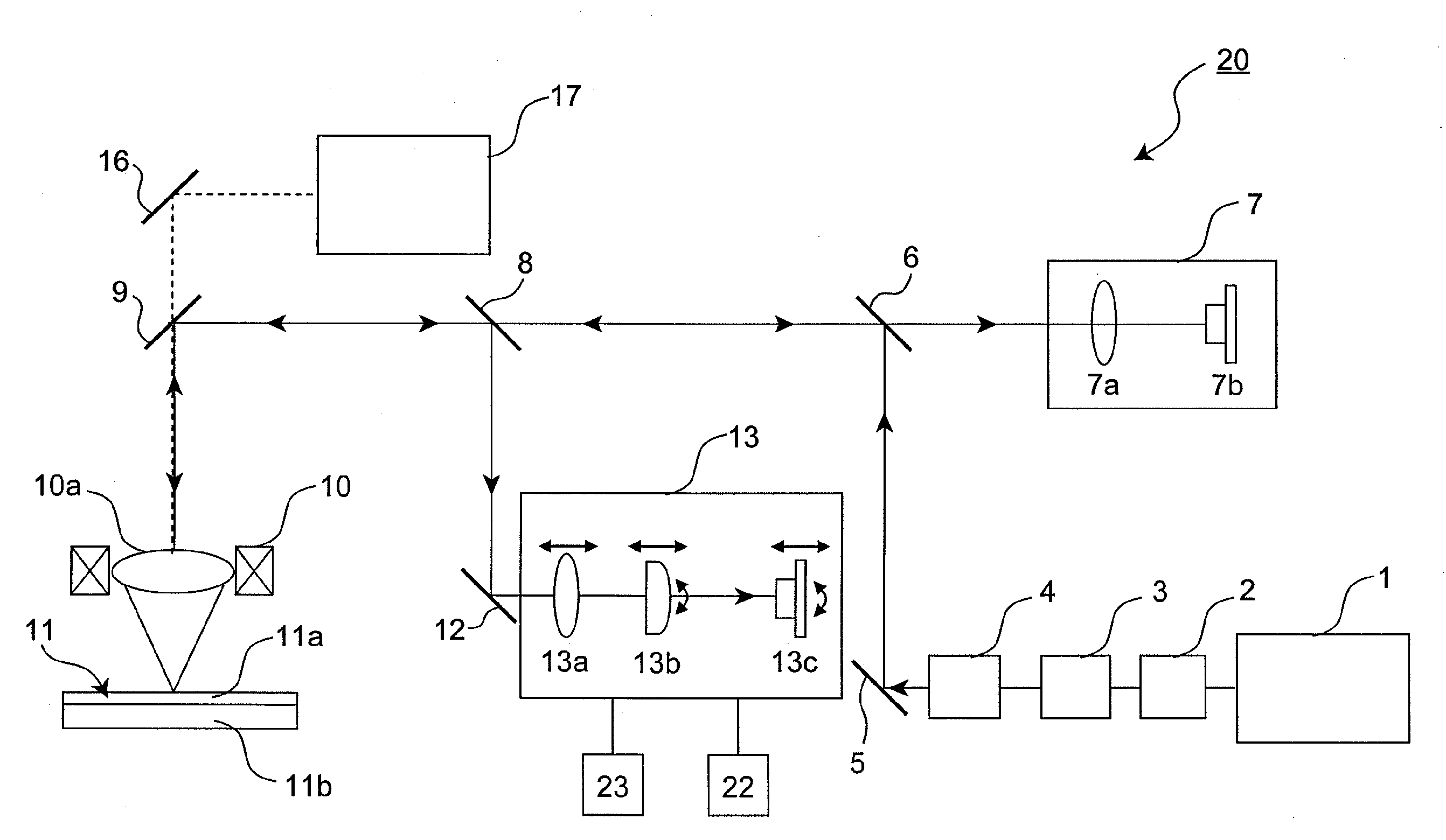
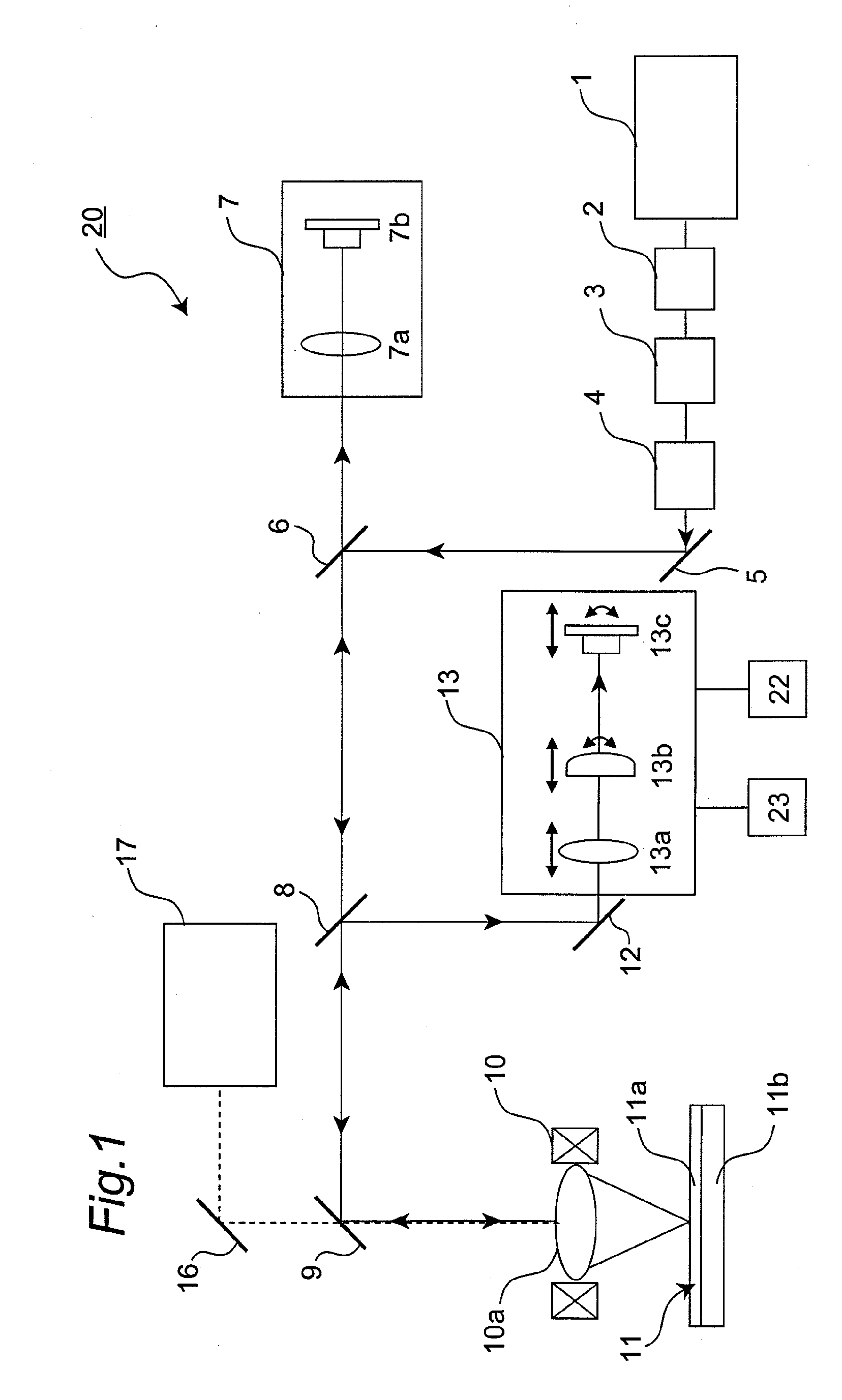
[0083]An example in which the configuration of the focus optical system of the embodiment shown in FIGS. 1 and 3 is applied to the optical disc master exposure apparatus 20 is described below.

[0084]The laser device 1 was provided by using a laser device having a wavelength of 266 nm, the power-controlling optical modulator 2 was provided by a power modulator using an electro-optic modulator (EOM) and a signal modulator using an acousto-optic modulator (AOM), and the optical polarizer 3 was provided by using an electro-optic deflector (EOD). Also, the beam shaping section 4 was provided by using two convex lenses having different focal lengths comprised of a front-side lens and a rear-side lens whose focal length was five times larger than that of the rear-side lens, and the objective lens 10a was provided by a lens having an NA of 0.9.

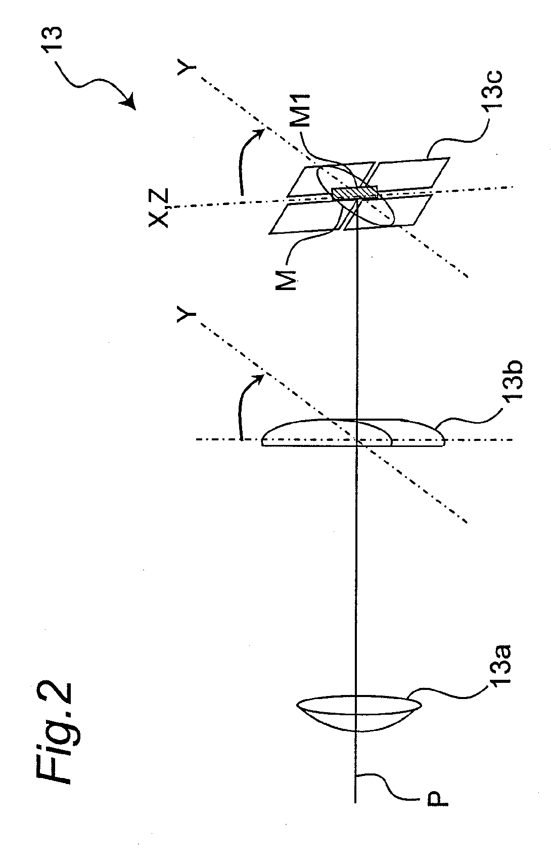
[0085]Further, the beam monitor optical system 7 was provided by using a CCD camera as the convex lens 7a and the CCD detector 7b, and the astigmatic ...


PUM

PropertyMeasurementUnit
thicknessaaaaaaaaaa
thicknessaaaaaaaaaa
thicknessaaaaaaaaaa

Abstract

In a focus optical system for optical discs or optical disc master exposure apparatuses, a relative positional relation between a cylindrical lens and a 4-division detector in an astigmatic optical system is adjust so that an interference fringe appearing in reflected light derived from an optical disc master is made to be incident on a dead zone of the 4-division detector. Thus, an astigmatic focus servo free from effects of variations in a focus error signal due to the interference fringe is realized. As a result of this, effects of the interference fringe appearing in the reflected light derived from an optical disc or optical disc master can be suppressed.

Description

BACKGROUND OF THE INVENTION[0001]1. Field of the Invention[0002]The present invention relates to a focus optical system for optical discs or optical disc master exposure apparatuses to be used for mass production of optical discs.[0003]2. Description of Related Art[0004]In production of optical discs, a stamper is first prepared by using a glass master as an optical disc master, and then copied reproduction of optical discs is performed by injection molding with use of the prepared stamper. Also, by an optical disc master exposure apparatus, recording light is projected to a recording layer (resist film) provided on the optical disc master to make the recording layer exposed to light, by which information is recorded on the optical disc master.[0005]In such an optical disc master exposure apparatus, a coherent beam, which is light emitted (radiated) from a light source, is subjected to modulation or polarization in response to information to be recorded, thereby forming recording li...

Claims


Application Information

Patent Timeline
Patent Type & Authority Applications(United States)
IPC IPC(8): G11B7/135
CPCG11B7/261G11B7/0909
Inventor OMORI, TAKESHIKASSAI, TAKAAKIMAEBARA, KENJIFUJITA, KEIJIASHIWA, HIROAKI
Owner PANASONIC CORP
Why Eureka
Try Eureka