Biopolymer crystal mounting device and manufacturing method thereof

a technology of biopolymer crystals and mounting devices, which is applied in the direction of polycrystalline material growth, material analysis using wave/particle radiation, instruments, etc., can solve the problems of inability to collect data, inability to manufacture, and inability to efficiently manufacture proteins, etc., to improve the effectiveness and accuracy of crystallography, and the effect of high yield

Inactive Publication Date: 2005-01-27
PROTEIN WAVE
View PDF2 Cites 4 Cited by
  • Summary
  • Abstract
  • Description
  • Claims
  • Application Information

AI Technical Summary

Benefits of technology

[0011] The present invention was made in consideration of the circumstances as discussed above, and has an object of providing an apparatus for a mounting biopolymer crystal, being an apparatus taking the place of the tool having been conventionally used for the purpose of taking a biopolymer crystal having been grown in a solution containing a biopolymer out of the solution, which can be manufactured efficiently without requiring labors, achieving a high yield, and which is capable of being mass-produced and improving effectiveness and accuracy in crystallography. Further, the invention has another object of providing a manufacturing method of a biopolymer crystal mounting device by which such a biopolymer crystal mounting device mounting can be successfully manufactured.

Problems solved by technology

A crystal of protein, however, is extremely soft inherently, and possesses brittle properties.
In case where the taking out a crystal and treatments in each step of freezing thereof are defective when collecting X-ray diffraction data, the crystal having been grown all the way will be broken, or minute cracks will be made within the crystal, resulting in a trouble that data cannot be collected.
Since the tool 9 is manually fabricated in such a way, the fabrication thereof is extremely inefficient, and requires much time.
Moreover, a burden of labors on a worker is large in the manual fabrication.
Furthermore, a loop may be manufactured to be inaccurate in diameter resulting in the reduction in yield.
A further problem exists in that the tool 9 cannot be mass-produced since the tool 9 is fabricated in manual works.
(2) Since fibers forming a nylon loop is approximately 10 μm to 20 μm in diameter, as shown in FIG. 10(d), the nylon loop is vibrated due to the wind pressure of a liquid nitrogen gas stream F when a crystal is retained in the ring 8a of the tool 9 and the crystal is frozen, leading to a further problem that diffraction data cannot be collected.

Method used


Image

  • Biopolymer crystal mounting device and manufacturing method thereof
  • Biopolymer crystal mounting device and manufacturing method thereof
  • Biopolymer crystal mounting device and manufacturing method thereof

Examples


examples

[0058] Hereinafter, more specific examples according to the invention are described.

[0059] [Example of Fabrication of Device]

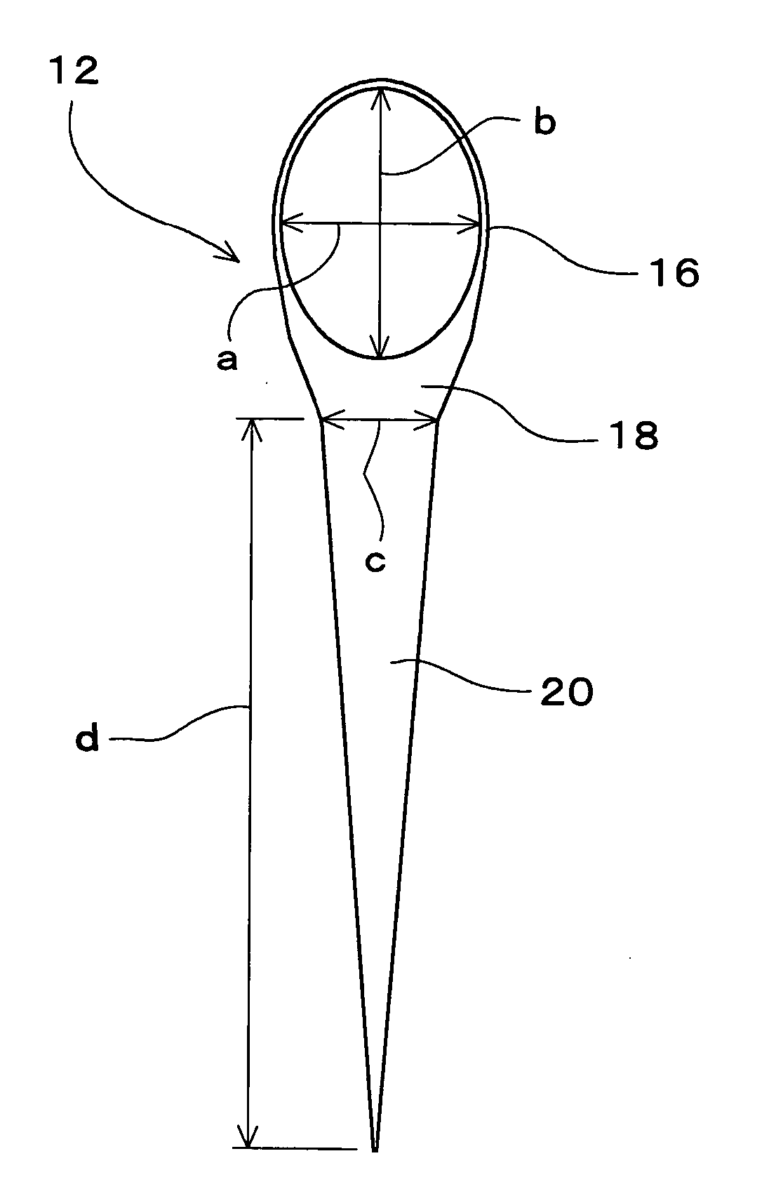
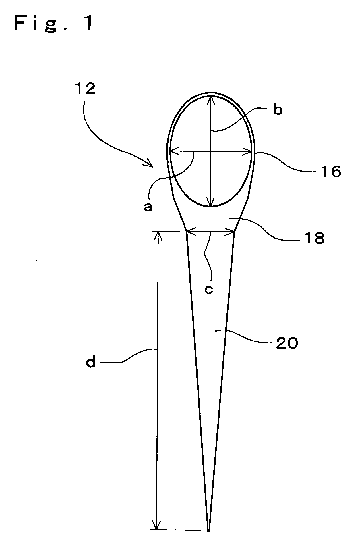
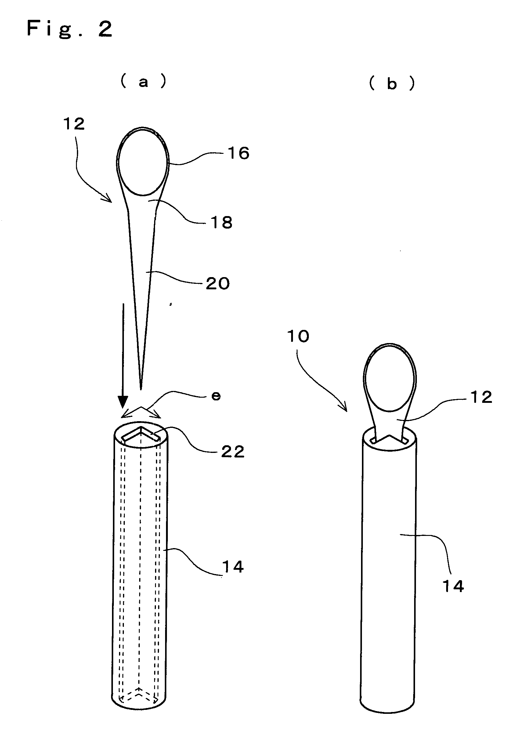
[0060] As a starting material, a square-shaped polyimide film having a 25 μm thickness and a side dimension of 120 mm was employed. This polyimide film was machined into a film member 12 of a pattern configuration as shown in FIG. 1. The loop portion 16 of the film member 12 was formed to be in the following sizes: a=0.8 mm; b=1.2 mm; average diameter D=1.0 mm. The minimum line width forming the loop portion 16 was 10 μm. Besides, a width c of the neck portion 18 was 0.6 mm, and a length d of the body portion 20 was 3 mm. Such a film member 12 was manufactured in the method as follows.

[0061] The above-mentioned polyimide film was mounted on and secured to a glass substrate of 1 mm in thickness. A metal thin-film of Ni·Cr alloy of 100 nm in film thickness was formed on the surface of this polyimide film by sputtering. Next, a positive type photo-resist was ap...


PUM

PropertyMeasurementUnit
volumeaaaaaaaaaa
diameteraaaaaaaaaa
diameteraaaaaaaaaa

Abstract

The invention provides a biopolymer crystal mounting device with which a biopolymer crystal having been grown in a solution containing a biopolymer can be taken out of the solution. The device can be manufactured efficiently without requiring labors and can be mass-produced with high yield. A biopolymer crystal mounting device comprises: a film member 12, which is made of a material possessing permeability to an electromagnetic wave, and which is integrally formed of a loop portion 16 holding a drop of solution containing a biopolymer crystal, a neck portion 18 and a body portion 20; and a tubular member 14 including a bearing hole 22 in which the body portion of the film member is inserted and supported. Further, the film member is inserted into and secured to the tubular member.

Description

BACKGROUND OF THE INVENTION [0001] 1. Field of the Invention [0002] The present invention relates to a biopolymer crystal mounting device to be used for taking a biopolymer crystal out of a solution and mounting it at the time of providing the biopolymer crystal having been grown in the solution containing a biopolymer typically represented by a protein for use in crystallography, and to a method of manufacturing such device for mounting a crystal thereof. [0003] 2. Description of the Related Art [0004] Making clear a three-dimensional structure of a biopolymer typically represented by a protein, not only enables to elucidate physiological functions of the biopolymer in vivo, but also is extremely useful for the purpose of advancing a rational development of drugs (drug design). As a practical method for analyzing a three-dimensional structure of the biopolymer, there have been an NMR (nuclear magnetic resonance) and an X-ray crystallography. From the viewpoint of analysis, the X-ra...

Claims


Application Information

Patent Timeline
Patent Type & Authority Applications(United States)
IPC IPC(8): C30B7/00C30B29/58G01N23/20
CPCC30B7/00G01N23/20025Y10T117/10Y10T117/1004C30B29/58
Inventor SANJOH, AKIRA
Owner PROTEIN WAVE
Why Eureka
Try Eureka