Branch Vessel Suture Stent System and Method

a stent and clamping technology, applied in the field of clamping vessel suture stent system and method, can solve the problems of long recovery time, complex surgical procedure, and long hospital stay

Inactive Publication Date: 2009-10-22
MEDTRONIC VASCULAR INC
View PDF11 Cites 128 Cited by
  • Summary
  • Abstract
  • Description
  • Claims
  • Application Information

AI Technical Summary

Benefits of technology

[0013]Another aspect according to the present invention provides a method of stenting a branch vessel off a main vessel, the method including providing a main vessel stent graft having main vessel stent graft material and a main vessel stent graft lumen; deploying the main vessel stent graft in the main vessel; providing a branch vessel suture stent in a stressed state, the branch vessel suture stent having a stent body and shape memory hooks, the stent body having a first end including a first periphery, the shape memory hooks being disposed about the first periphery; advancing the branch vessel suture stent through a fenestration in the main vessel stent graft to locate the stent body in the branch vessel and the shape memory hooks in the main vessel stent graft lumen; and allowing the seal portion of the stent to expand and then relaxing each of the shape memory hooks to engage the main vessel stent graft material and form a loop.

Problems solved by technology

While open surgery is an effective surgical technique in light of the risk of a fatal abdominal aortic aneurysm rupture, the open surgical technique suffers from a number of disadvantages.
The surgical procedure is complex, requires a long hospital stay, requires a long recovery time, and has a high morbidity and mortality rates.
Although often referred to as stent grafts, these tubular endoluminal prostheses differ from covered stents in that they are not used to mechanically prop open natural blood vessels.
In such arrangements, a joint created in situ between the stent graft and the branched conduit is prone to leakage, reducing flow to the branch vessels and continuing to pressurize the aneurysmal sac.
This approach has its own problems, however, since each stent graft is different, requiring a customized stent graft constructed using individualized personal measurements and construction.
In addition, the bulky customized stent grafts are difficult to deploy, since the branch conduits are attached before deployment and thus make the device so much more bulky.
This approach has problems because complicated sealing mechanisms are required and limited working space is available in the vessel.
Flaring is however technically complex and time consuming to implement.
Another approach has been to use a grommet or fitting crimped across the graft material, but such fittings are complex and difficult to deploy.
Another problem is fixation of the branch vessel stent at the visceral artery.

Method used


Image

  • Branch Vessel Suture Stent System and Method
  • Branch Vessel Suture Stent System and Method
  • Branch Vessel Suture Stent System and Method

Examples


Embodiment Construction

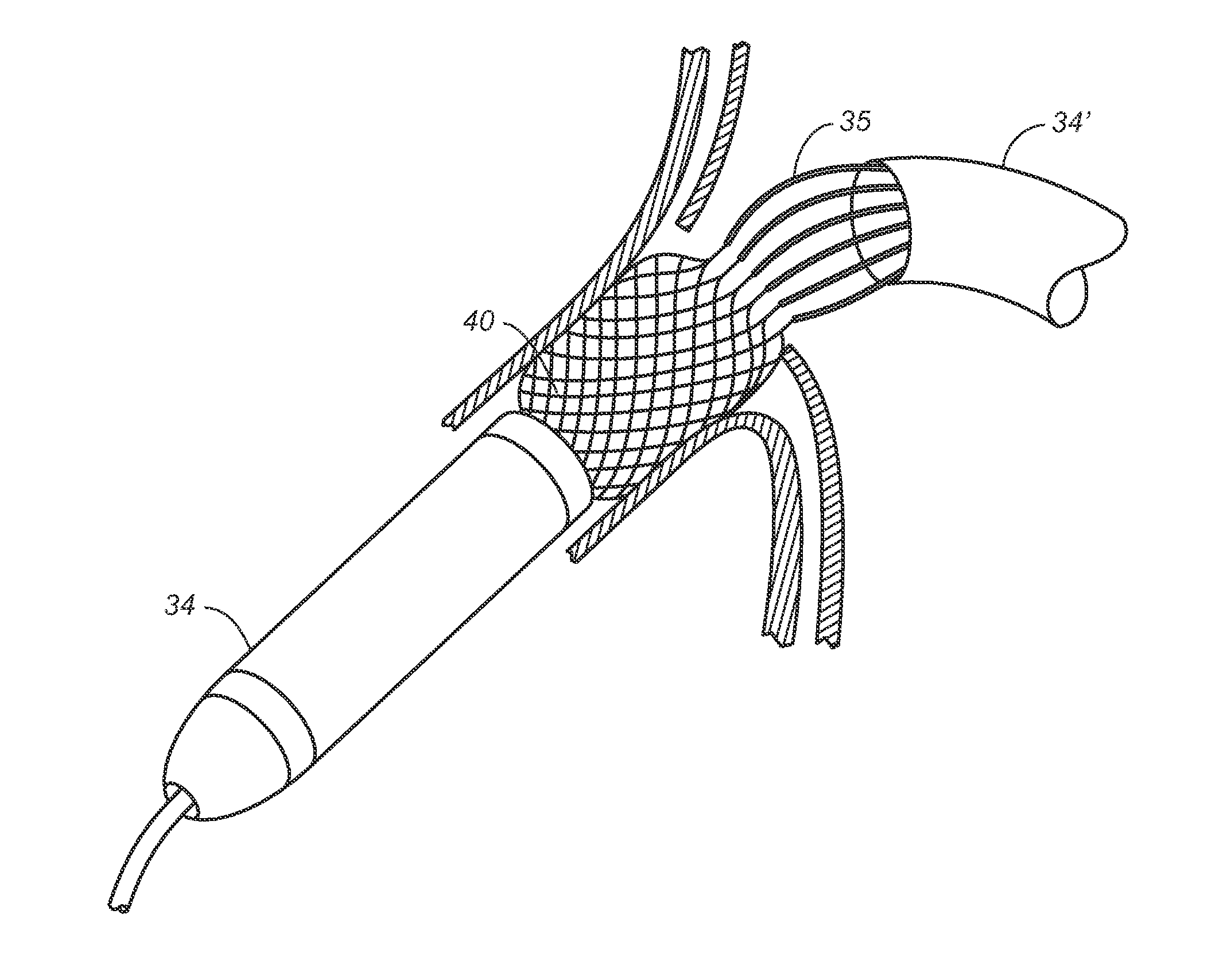
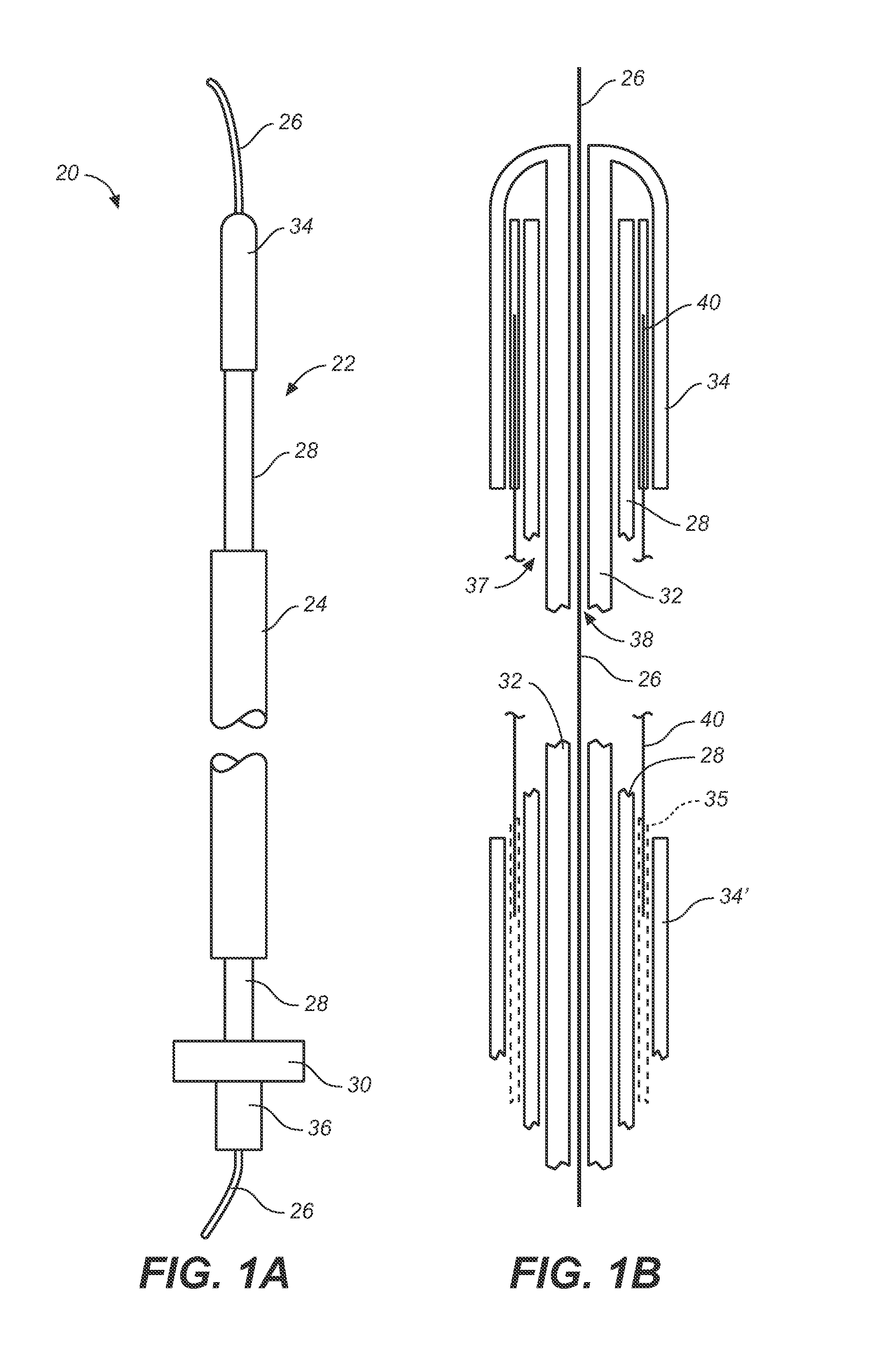
[0026]FIGS. 1A-1B are side and close up cross sectional views, respectively, of a branch vessel suture stent system. The branch vessel suture stent system 20 includes a suture stent delivery catheter 22 for delivering and deploying a branch vessel suture stent 40, a steerable catheter 24, and a guidewire 26. The suture stent delivery catheter 22 includes an outer shaft 28, an inner shaft 32, and a sheath (distal sheath 34 and proximal sheath 34′). The distal sheath 34 restrains the branch vessel suture stent 40 in a compressed (stressed) state until the branch vessel suture stent 40 is in position for deployment. When the proximal sheath 34′ is moved proximally to expose the hypotubes containing the hooks, the positioning of the proximal end of the suture stent 40 can be verified. Then the distal sheath 34 is moved distally to release the body of the branch vessel suture stent 40 to allow it to relax toward its parent state. The suture stent is prevented from moving forward with the...


PUM


Abstract

A branch vessel suture stent system and method including a branch vessel suture stent having a stent body having a first end, a second end, and a central axis, the first end having a first periphery; and shape memory hooks disposed about the first periphery, each of the shape memory hooks being attached to the first periphery at an attachment point, the shape memory hooks being elongated in a stressed state and looped in a parent state, each of the shape memory hooks defining a loop plane in the parent state. The shape memory hooks are substantially parallel to the central axis in the stressed state, and the first periphery at the attachment point for each of the shape memory hooks is substantially orthogonal to the loop plane for each of the shape memory hooks in the parent state. The delivery system allows the main body of the branch device to expand while maintaining the hooks in an undeployed configuration using individual hypotubes. Then once the body of the suture stent has expanded allowing the suture stent shape memory hooks to be released and engage the main graft body and / or surrounding tissue.

Description

TECHNICAL FIELD[0001]The technical field of this disclosure is medical implantation devices, particularly, a branch vessel suture stent system and method.BACKGROUND OF THE INVENTION[0002]Wide ranges of medical treatments have been developed using endoluminal prostheses, which are medical devices adapted for temporary or permanent implantation within a body lumen, such as naturally occurring or artificially made lumens. Examples of lumens in which endoluminal prostheses may be implanted include arteries such as those located within coronary, mesentery, peripheral, or cerebral vasculature; veins; gastrointestinal tract; biliary tract; urethra; trachea; hepatic shunts; and fallopian tubes. Various types of endoluminal prostheses have also been developed with particular structure to modify the mechanics of the targeted luminal wall.[0003]A number of vascular devices have been developed for replacing, supplementing, or excluding portions of blood vessels. These vascular devices include e...

Claims


Application Information

Patent Timeline
Patent Type & Authority Applications(United States)
IPC IPC(8): A61F2/06A61F2/82A61F2/90
CPCA61F2/064A61F2/90A61F2/95A61F2002/075A61F2002/821D10B2509/06A61F2002/9665D04C1/06A61F2220/0008A61F2220/0016A61F2230/0054A61F2002/8486
Inventor BRUSZEWSKI, WALTER
Owner MEDTRONIC VASCULAR INC
Why Eureka
Try Eureka