Vane-type cam phaser having staged locking pins to assist intermediate position locking

Active Publication Date: 2009-10-29
DELPHI TECH IP LTD
View PDF4 Cites 21 Cited by
  • Summary
  • Abstract
  • Description
  • Claims
  • Application Information

AI Technical Summary

Benefits of technology

[0007]Briefly described, a vane-type camshaft phaser in accordance with the invention for varying the timing of combustion valves in an internal combustion engine includes a pre-loaded bias spring to urge the rotor toward an intermediate locking position from any rotational position retarded of the locking position. The rotor comprises a primary locking pin and a secondary locking pin for mating with respective primary and secondary locking pin seats in the phaser stator, the first and second locking pins being non-coaxially acting. The primary seat is elongated and therefore is readily located by the primary locking pin to provide a first limit to the rotor phase angle authority in the retard direction when t

Problems solved by technology

A known problem in such phasers is that there is no mechanical means such as a stop to assist in positioning the rotor for locking in an intermediate position; thus, locking is not

Method used


Image

  • Vane-type cam phaser having staged locking pins to assist intermediate position locking
  • Vane-type cam phaser having staged locking pins to assist intermediate position locking
  • Vane-type cam phaser having staged locking pins to assist intermediate position locking

Examples


Embodiment Construction

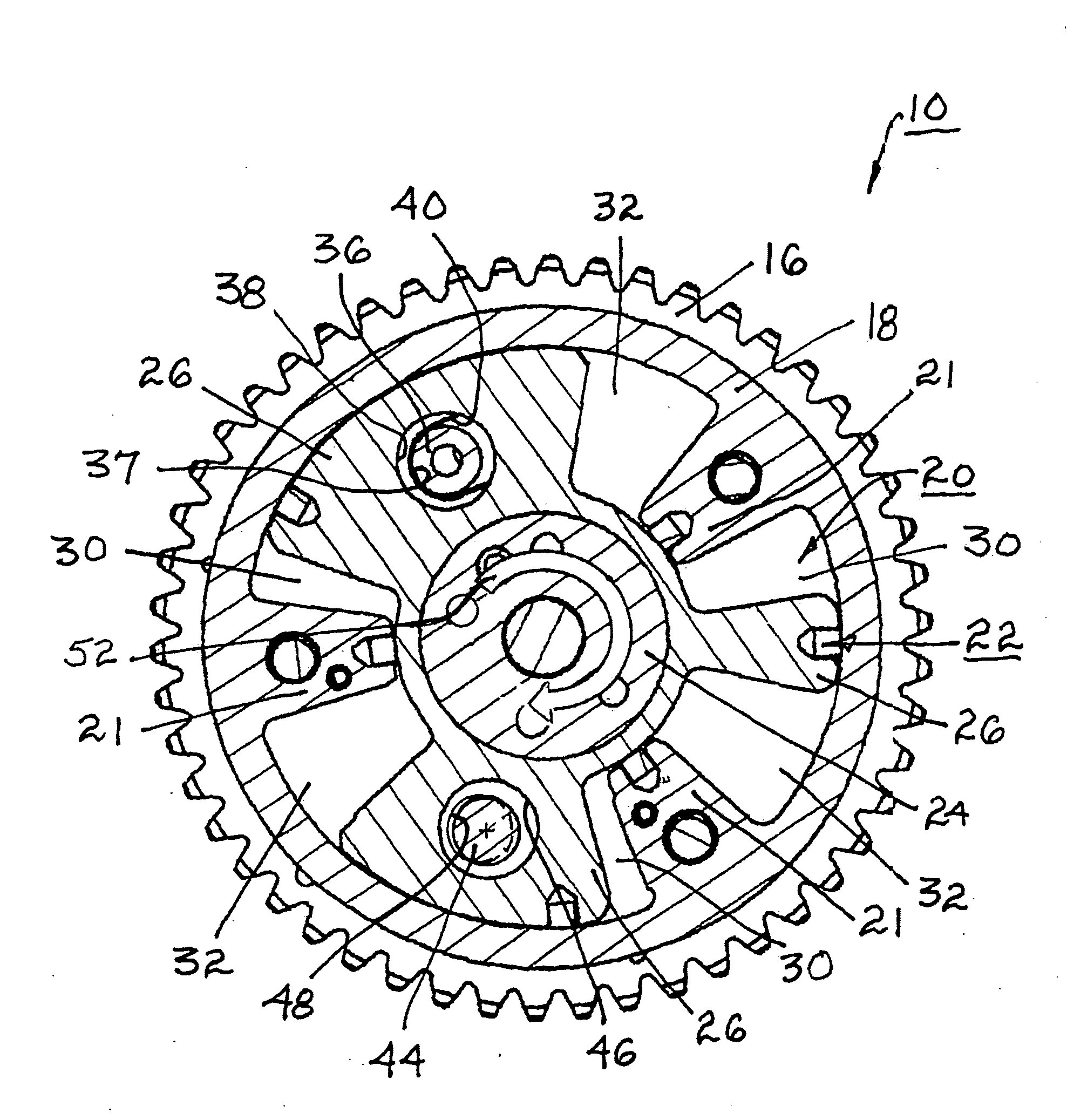
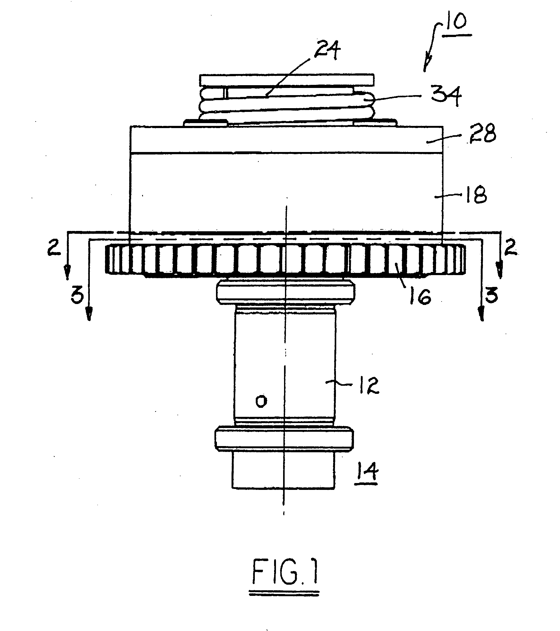
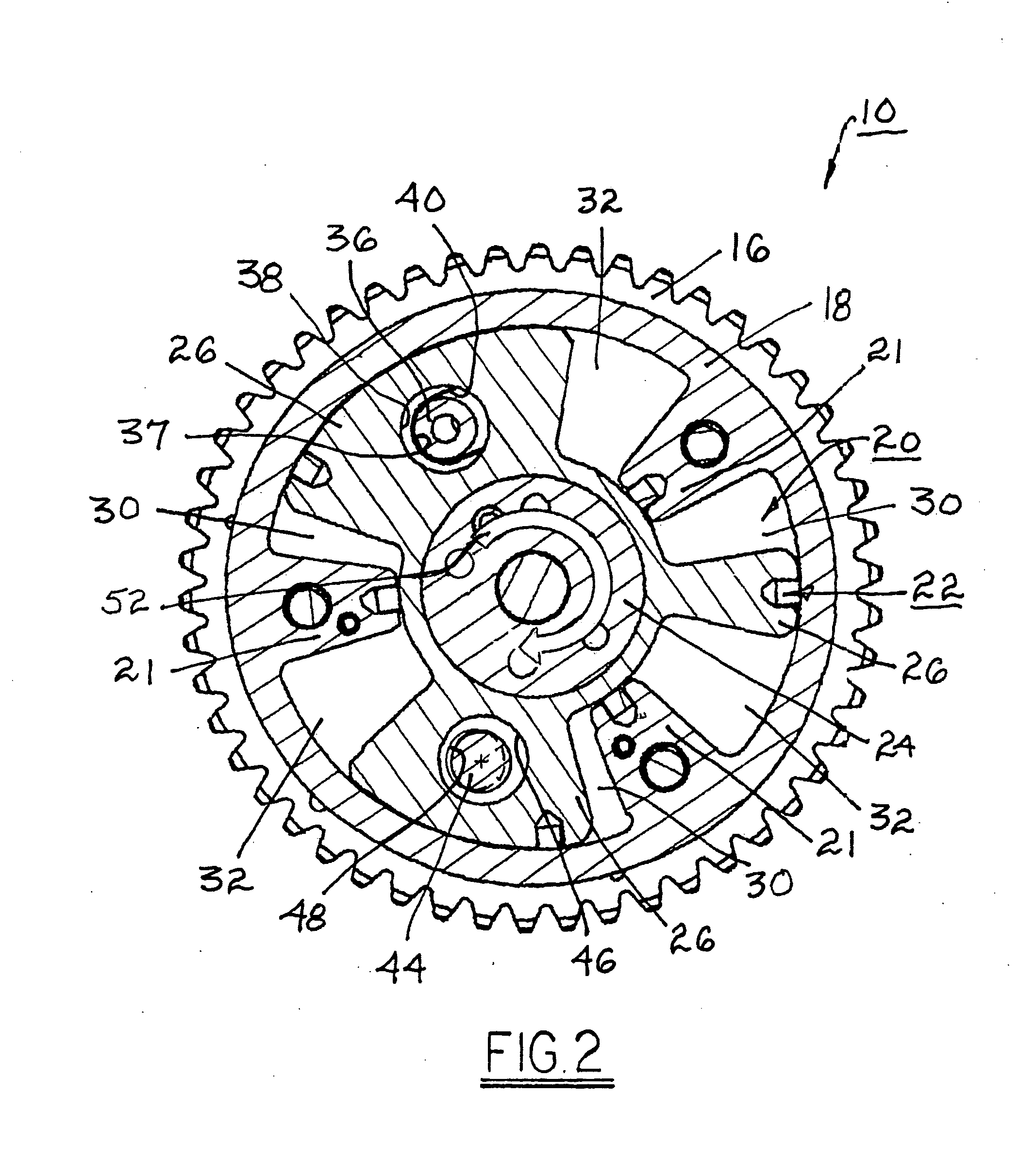
[0012]Referring to FIGS. 1 and 2, a vane-type camshaft phaser 10 in accordance with the present invention is shown as mounted on the end of a camshaft 12 of an internal combustion engine 14. Phaser 10 includes a pulley or sprocket 16 for engaging a timing chain or belt (not shown) operated by an engine crankshaft (not shown). A stator 18 is disposed against pulley / sprocket 16 and is rotationally immobilized with respect to pulley / sprocket 16 (and may be formed integral therewith). Stator 18 is provided with a central chamber 20, subdivided by a plurality of inwardly-extending spaced-apart lobes 21, for receiving a rotor 22 having a hub 24 and a plurality of spaced-apart vanes 26 extending radially therefrom. Central chamber 20 is closed by a cover plate 28, forming advance and retard chambers 30,32 between the rotor and the stator. A torsional bias spring 34 is mounted on hub 24 and grounded at a first end thereto and at a second end to cover plate 28, which is bolted to stator 18. ...


PUM


Abstract

A vane-type camshaft phaser including a bias spring to urge the rotor toward an intermediate locking position from any rotational position retarded of the locking position. The rotor comprises non-coaxially acting primary and secondary locking pins for mating with primary and secondary locking pin seats in the phaser stator. The primary seat is elongated and is readily located by the primary locking pin to provide a first limit to the rotor phase angle authority in the retard direction. Camshaft torque reversals cause the rotor phase angle to dither. With each torque reversal the secondary locking pin passes over its seat, allowing multiple opportunities for re-engagement. The clearance of the secondary locking pin to its seat defines the rotary lash in the phaser.

Description

TECHNICAL FIELD[0001]The present invention relates to vane-type camshaft phasers for varying the phase relationship between crankshafts and camshafts in internal combustion engines; more particularly, to such phasers wherein a locking pin is utilized to lock the phaser rotor with respect to the stator at certain times in the operating cycle; and most particularly, to a phaser having staged locking pins to reliably lock a phaser rotor at a rotational position intermediate between full timing advance and full timing retard positions.BACKGROUND OF THE INVENTION[0002]In a typical prior art vane-type cam phaser, a controllably selective locking pin is slidingly disposed in a bore in a rotor vane to permit rotational locking of the rotor to the stator (or sprocket wheel or pulley) under certain conditions of operation of the phaser and engine. In older prior art phasers, it is desired that the rotor be locked at an extreme of the rotor authority, typically at the full retard position. In ...

Claims


Application Information

Patent Timeline
IPC IPC(8): F01L1/344
CPCF01L1/3442F01L2001/34483F01L2001/34469
Inventor FISCHER, THOMAS H.
Owner DELPHI TECH IP LTD
Why Eureka
Try Eureka