
Mitigation of deposits and secondary reactions in thermal conversion processes

a thermal conversion and secondary reaction technology, applied in mechanical equipment, lighting and heating equipment, liquid cleaning, etc., can solve the problems of reducing the yield of two-phase tar-aqueous mixtures, reducing the efficiency of thermal conversion processes, and reducing the number of secondary thermal reactions. , to achieve the effect of reducing cumulative deposition and unwanted secondary thermal reactions

Active Publication Date: 2009-10-29
ENSYN RENEWABLES
View PDF11 Cites 21 Cited by
  • Summary
  • Abstract
  • Description
  • Claims
  • Application Information

AI Technical Summary

Benefits of technology

[0009]Described herein are systems and methods for reducing cumulative deposition and unwanted secondary thermal reactions in pyrolysis and other thermal conversion processes.
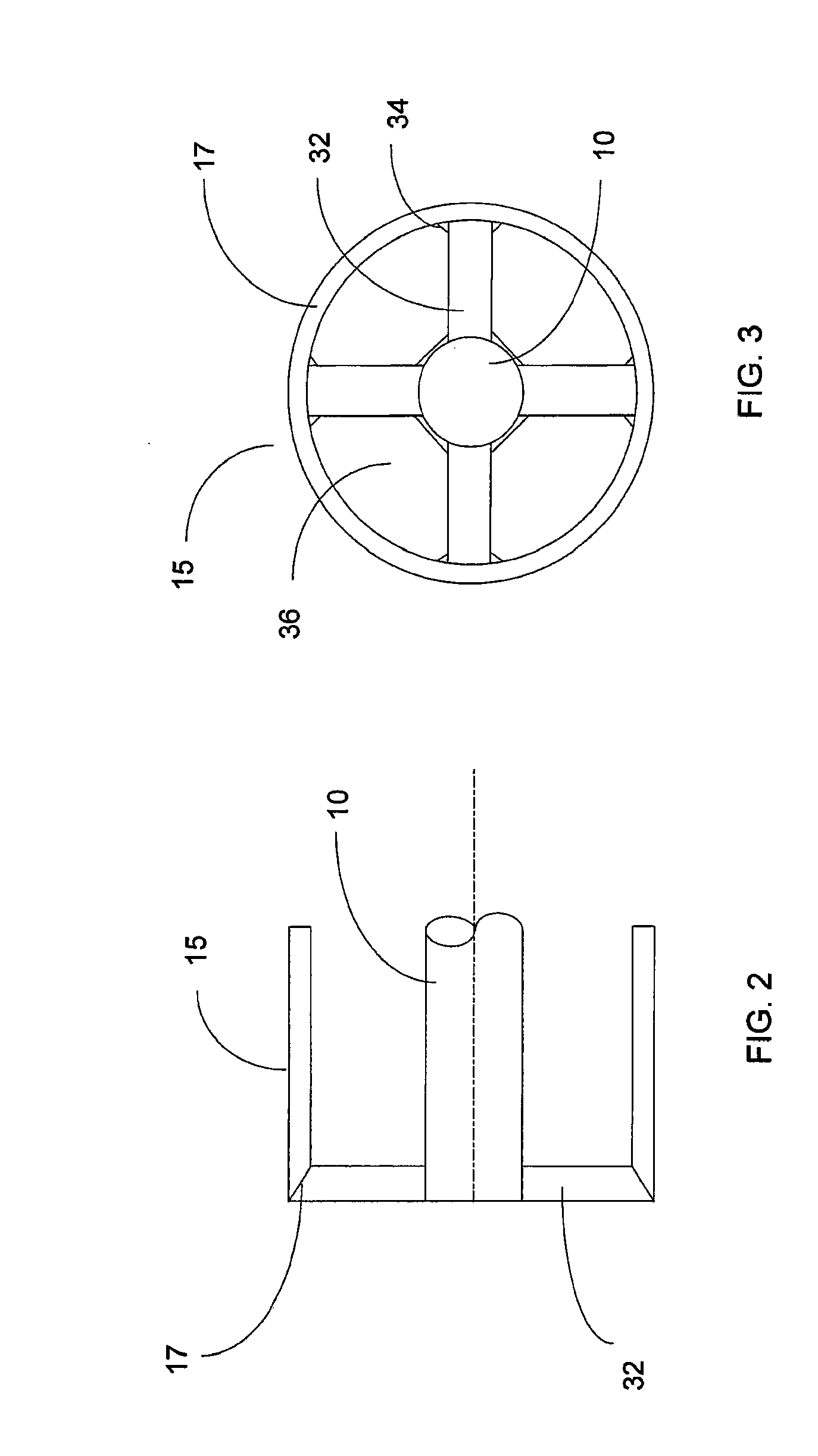
[0010]In an embodiment, a system comprises a device, referred to as a reamer, for removing product deposits between thermal conversion and condensation operations of a pyrolysis process. The reamer may comprise, but is not limited to, a mechanical reciprocating rod or ram, a mechanical auger, a drill bit, a high-temperature wiper, brush, or punch to remove deposits and prevent secondary reactions. Alternatively or in addition, the reamer may use a high-velocity curtain or jet (i.e., a hydraulic or pneumatic stream) of steam, product gas, recycle gas, other gas jet or non-condensing liquid to remove deposits. Preferably, the reamer removes deposits during the pyrolysis process allowing for continuous operation of the pyrolysis process.

Problems solved by technology

This is in stark contrast to slow pyrolysis, which produces a thick, low quality, two-phase tar-aqueous mixture in very low yields.
If the desired vapor products are not rapidly quenched shortly after being produced, some of the constituents will crack to form smaller molecular weight fragments such as non-condensable gaseous products and solid char, while others will recombine or polymerize into undesirable high-molecular weight viscous materials and semi-solids.
As a general rule, the vapor-phase constituents will continue to react at an appreciable rate, and thermal degradation will be evident, at temperatures above 400° C. If a fast pyrolysis process is to be commercially viable, it is therefore extremely important to instantaneously quench the vapor stream, after a suitable reaction time, to a temperature below about 400° C. preferably less than 200° C. and more preferably less than 50° C. Such a requirement to rapidly cool a hot vapor stream is not easily accomplished in scaled-up commercial fast pyrolysis systems.
As the rapid cooling is effected, certain components in the vapor stream (particularly the heavier fractions) tend to quickly condense on cooler surfaces (i.e., transfer lines and ducting to the condensers) causing deposition and fouling of the equipment, and also resulting in the creation of a mass of warm liquid where additional secondary polymerization and thermal degradation can occur.

Method used


Image

  • Mitigation of deposits and secondary reactions in thermal conversion processes
  • Mitigation of deposits and secondary reactions in thermal conversion processes
  • Mitigation of deposits and secondary reactions in thermal conversion processes

Examples


Embodiment Construction

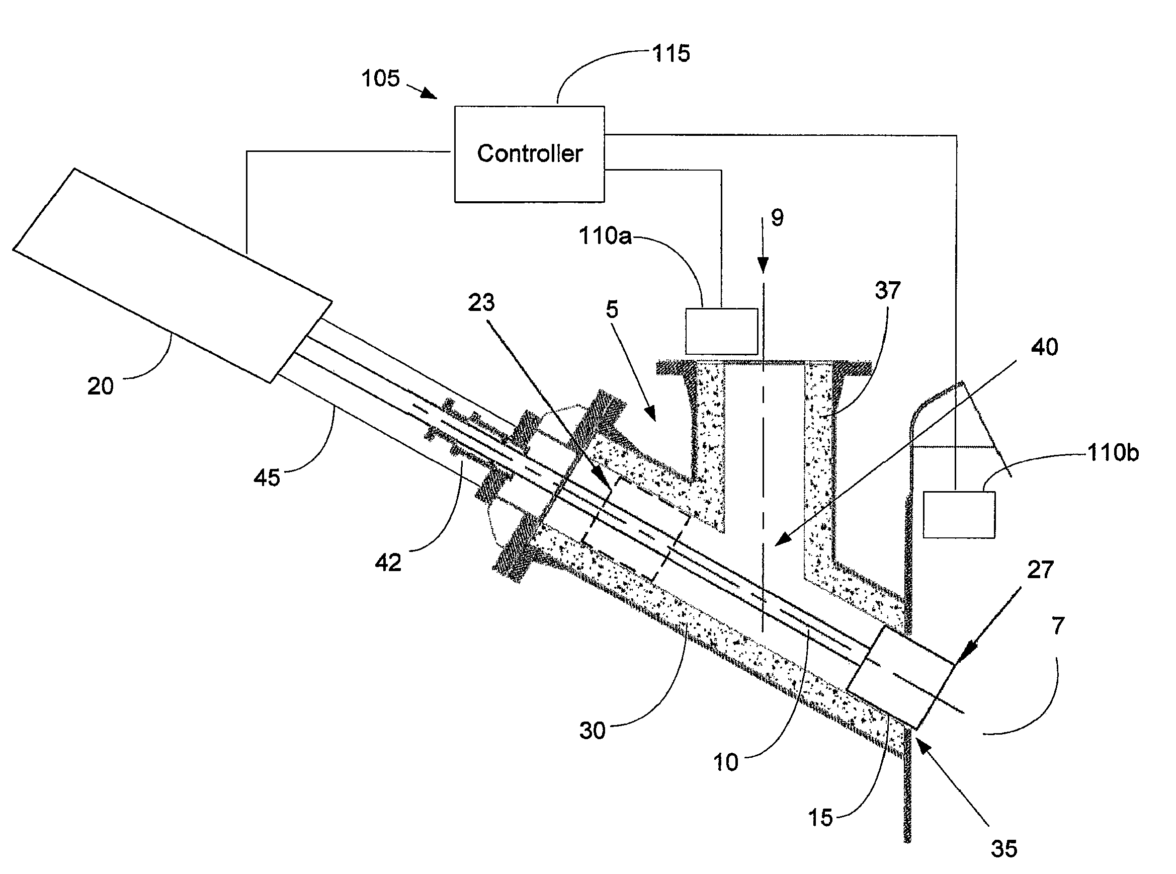
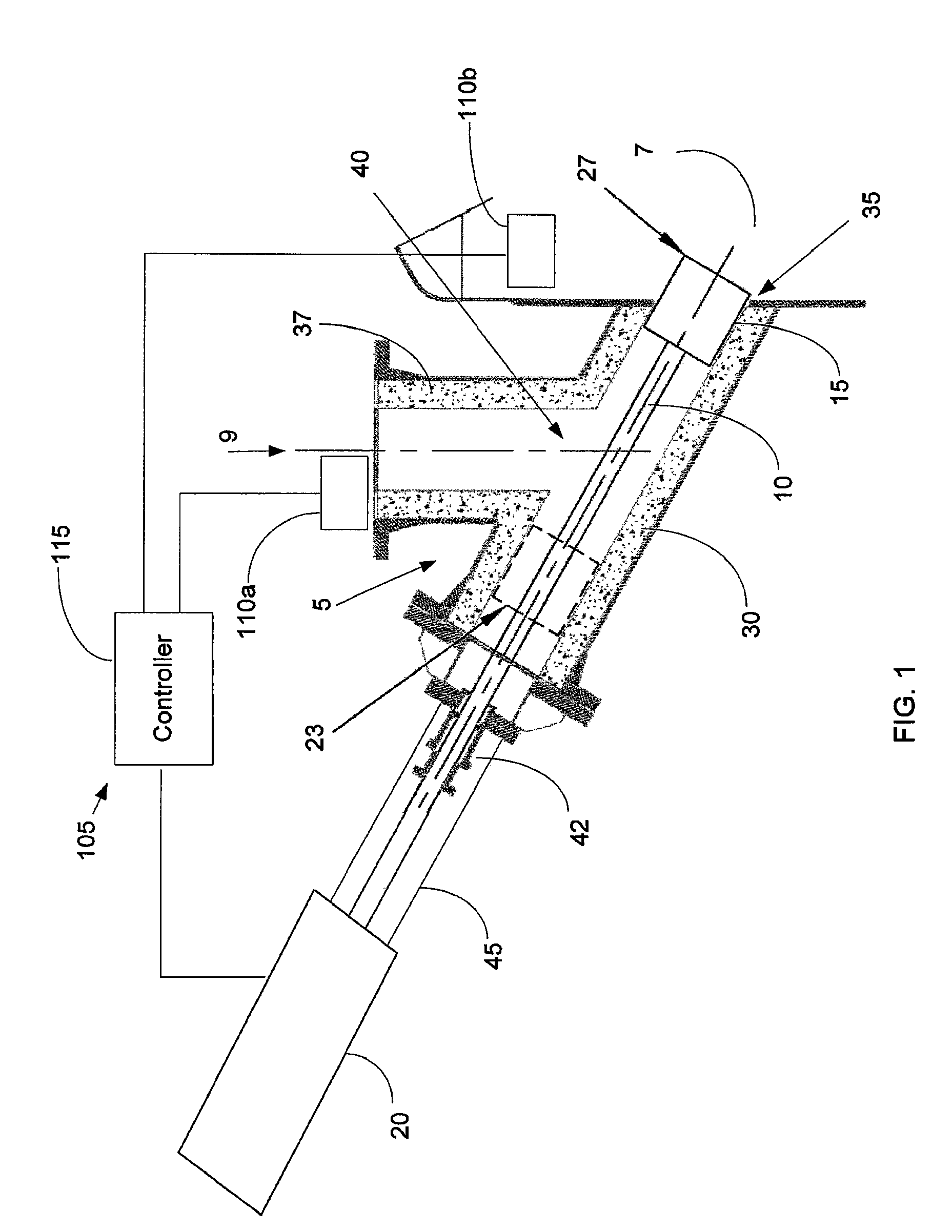
[0022]FIG. 1 shows a mechanical reamer according to an exemplary embodiment of the present invention. In this exemplary embodiment, the reamer is configured to clear material build up in a pipeline 5 used for transporting a hot vapor stream to a condensing column or chamber 7 in a pyrolysis process. Details of an exemplary pyrolysis process in which the reamer can be used are given in co-pending application Ser. No. 11 / 943,329, titled “Rapid Thermal Conversion of Biomass,” filed on Nov. 20, 2007, the specification of which is incorporated herein by reference.

[0023]The hot vapor stream flows through the pipeline 5 in the direction 9, and enters the condensing camber 7 where the hot vapor stream is quenched with a cool liquid to condense the hot vapor into a liquid product. A hot-cold interface zone forms around the interface between the pipeline 5 and the condensing camber 7. Due to the hot-cold interface zone, deposition of solid material (not shown) in the pipeline 5 occurs in the ...


PUM


Abstract

Described herein are systems and methods for reducing cumulative deposition and unwanted secondary thermal reactions in pyrolysis and other thermal conversion processes. In an embodiment, a system comprises a device, referred to as a reamer, for removing product deposits between thermal conversion and condensation operations of a pyrolysis process. The reamer may comprise, but is not limited to, a mechanical reciprocating rod or ram, a mechanical auger, a drill bit, a high-temperature wiper, brush, or punch to remove deposits and prevent secondary reactions. Alternatively or in addition, the reamer may use a high-velocity curtain or jet (i.e., a hydraulic or pneumatic stream) of vapor, product gas, recycle gas, other gas jet or non-condensing liquid to remove deposits. Preferably, the reamer removes deposits during the pyrolysis process allowing for continuous operation of the pyrolysis process.

Description

FIELD OF THE INVENTION[0001]The present invention is related to pyrolysis and other thermal conversion processes, and more particular to systems and method for reducing deposits and mitigating secondary reactions in pyrolysis and other thermal conversion processes.BACKGROUND OF THE INVENTION[0002]Biomass has been the primary source of energy over most of human history. During the 1800's and 1900's the proportion of the world's energy sourced from biomass dropped sharply, as the economical development of fossil fuels occurred, and markets for coal and petroleum products took over. Nevertheless, some 15% of the world's energy continues to be sourced from biomass, and in the developing world, the contribution of biomass to the energy supply is close to 38%.[0003]Solid biomass, typically wood and wood residues, is converted to useful products, e.g., fuels or chemicals, by the application of heat. The most common example of thermal conversion is combustion, where air is added and the ent...

Claims


Application Information

Patent Timeline
IPC IPC(8): B08B1/04B08B7/00B08B9/04B08B13/00F23J3/00B08B1/00
CPCB08B9/00F23J3/02B08B9/045B08B9/0436
Inventor FREEL, BARRYHOPKINS, GEOFFREY
Owner ENSYN RENEWABLES
Learn More