
Water Treatment Apparatus and Water Treatment Method

a technology of water treatment apparatus and water treatment method, which is applied in the direction of multi-stage water/sewage treatment, membranes, separation processes, etc., can solve the problems of increasing the treatment efficiency of the membrane device, clogging of the membrane, and conventional pretreatment without the function of maintaining a high dissolved oxygen concentration, etc., to prevent the effect of clogging

Inactive Publication Date: 2009-10-29
SHARP KK
View PDF11 Cites 13 Cited by
  • Summary
  • Abstract
  • Description
  • Claims
  • Application Information

AI Technical Summary

Benefits of technology

[0015]It is an object of the present invention to provide a water treatment apparatus and a water treatment method capable of carrying out treatment by raising the activity of the microorganisms propagating in a charcoal or a synthetic charcoal and reducing the organic loads and so on of a membrane device in a subsequent step.

Problems solved by technology

However, the conventional pretreatment does not have the function of maintaining a high dissolved oxygen concentration to the subsequent step for a long time by markedly raising the dissolved oxygen concentration in the water to be treated to carry out the treatment with improved activities of microorganisms.
Furthermore, the conventional pretreatment does not have the function of improving the functions of the microorganisms by markedly raising the dissolved oxygen concentration in the water to be treated and markedly raising the treatment efficiency of the membrane device in the subsequent stage.
Moreover, the conventional pretreatment, which has general aeration with a blower, does not have a treatment function with micro-nano bubbles that contain both micro bubbles of a diameter of not greater than 50 microns and not smaller than one micron and nano bubbles of a diameter of not greater than one micron.

Method used


Image

  • Water Treatment Apparatus and Water Treatment Method
  • Water Treatment Apparatus and Water Treatment Method
  • Water Treatment Apparatus and Water Treatment Method

Examples


first embodiment

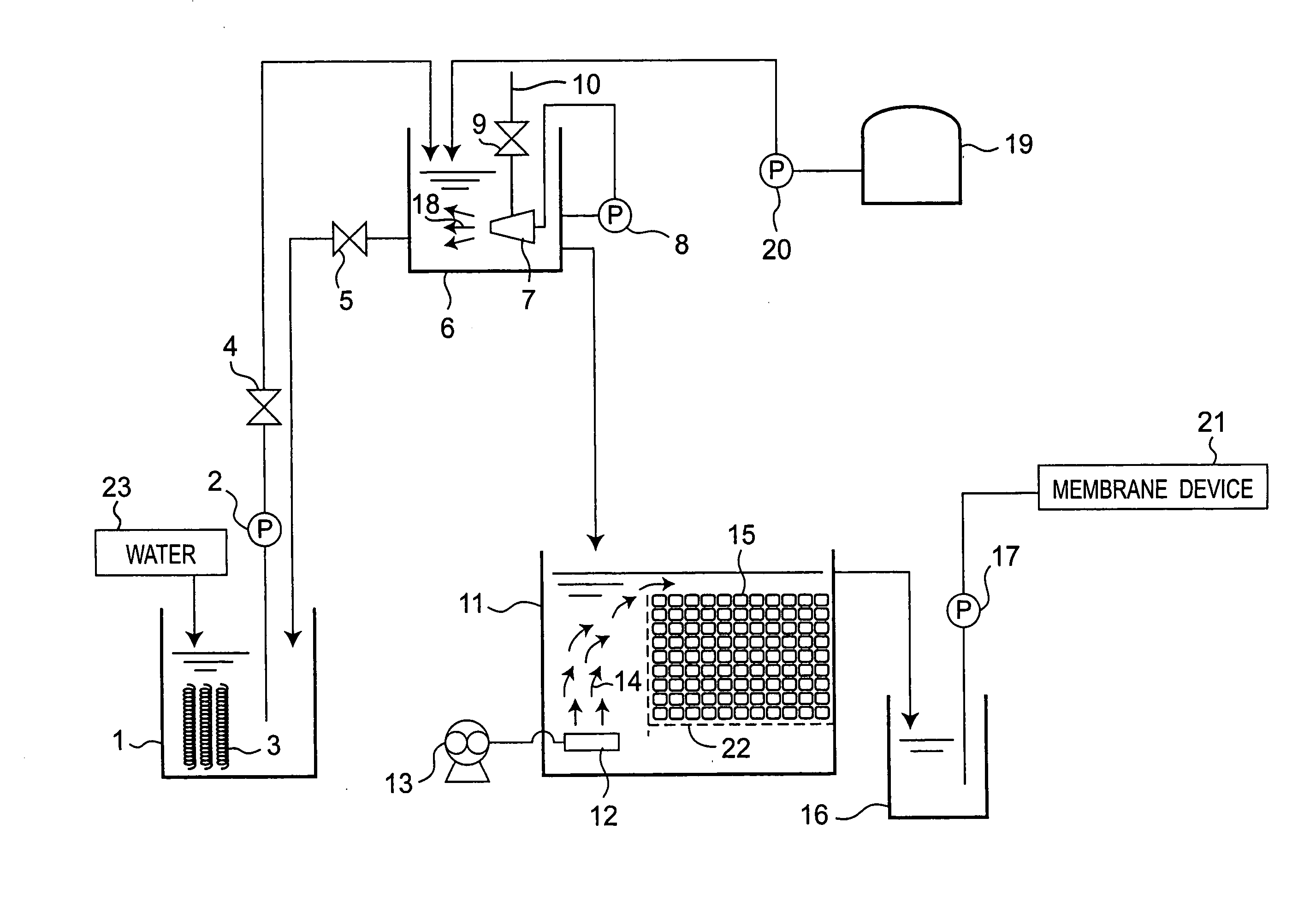
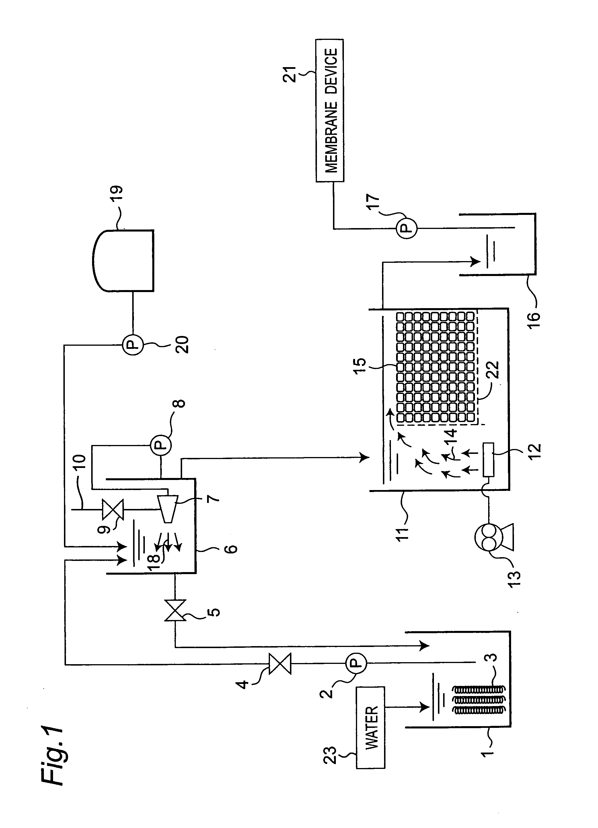
[0091]FIG. 1 shows the schematic construction of a water treatment apparatus of the present embodiment. In FIG. 1, a reference numeral 1 denotes a raw water tank of a liquid, and a pump 2 that pumps up the liquid is provided. It is herein noted that the liquid in the present embodiment is defined widely as “water”23. It is noted that the “water”23, of course, includes “service water” and “waste water”.

[0092]The raw water tank 1 is internally filled with a polyvinylidene chloride filler 3. Then, the water 23 introduced into the raw water tank 1 is discharged by the pump 2 with its discharge rate adjusted by a valve 4 and is introduced into a micro-nano bubble generation tank 6.

[0093]A micro-nano bubble generator 7 is placed in the micro-nano bubble generation tank 6, and micro-nano bubbles are generated by the micro-nano bubble generator 7, generating micro-nano bubble streams 18 in the micro-nano bubble generation tank 6.

[0094]A circulating pump 8 is placed outside the micro-nano bu...

second embodiment

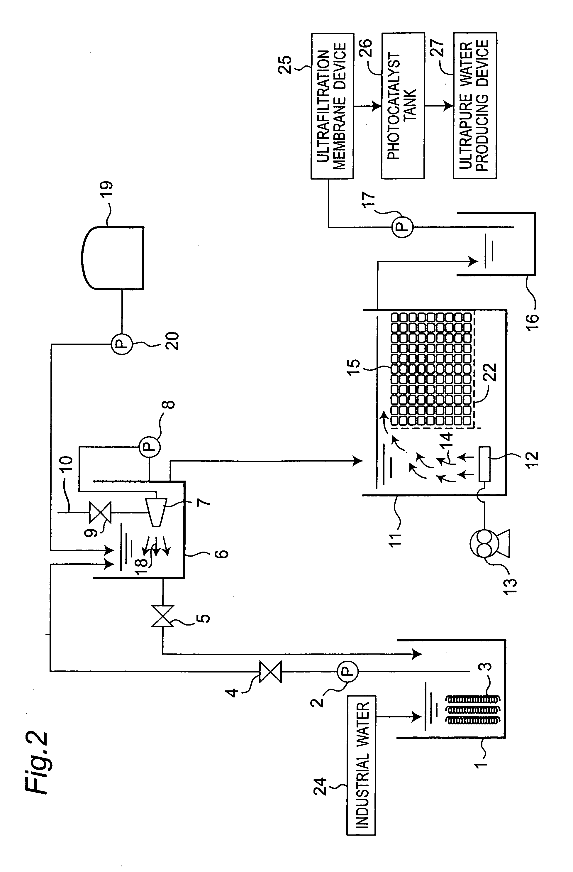
[0103]FIG. 2 shows the schematic construction of a water treatment apparatus of the present embodiment.

[0104]In contrast to the fact that the liquid supplied to the raw water tank 1 has been defined widely as the water 23 in the first embodiment, the liquid is limited to industrial water 24 in the present embodiment. Moreover, an ultrafiltration membrane device 25 is specifically employed as the membrane device 21 of the first embodiment. Furthermore, a photocatalyst tank 26 and an ultrapure water producing device 27 are arranged in this order following the ultrafiltration membrane device 25.

[0105]The components other than the above are the same as in the first embodiment and denoted by the same reference numerals as in the first embodiment with no detailed description provided therefor.

[0106]As described above, in the present embodiment, the liquid supplied to the raw water tank 1 is limited to the industrial water 24. Therefore, the present embodiment is a water treatment apparatu...

third embodiment

[0109]FIG. 3 shows the schematic construction of a water treatment apparatus of the present embodiment.

[0110]In contrast to the fact that the liquid supplied to the raw water tank 1 has been defined widely as the water 23 in the first embodiment, the liquid is limited to waste water 28 in the present embodiment. Moreover, a microfiltration membrane device 29 is specifically employed as the membrane device 21 of the first embodiment. Furthermore, the photocatalyst tank 26 and the ultrapure water producing device 27 are arranged in this order following the microfiltration membrane device 29.

[0111]The components other than the above are the same as in the first embodiment and denoted by the same reference numerals as in the first embodiment with no detailed description provided therefor.

[0112]As described above, in the present embodiment, the liquid supplied to the raw water tank 1 is limited to the waste water 28. Therefore, the present embodiment is a water treatment apparatus for th...


PUM

PropertyMeasurementUnit
diameteraaaaaaaaaa
diameteraaaaaaaaaa
specific gravityaaaaaaaaaa

Abstract

Water (23) that contains micro-nano bubbles generated in a micro-nano bubble generation tank (6) is introduced and treated in a charcoal water tank (11) which is filled with a charcoal (15) and in which an air diffusing pipe (12) is placed and thereafter introduced and treated in a membrane device (21). Thus, activities of microorganisms propagating in the charcoal (15) are increased by the micro-nano bubbles, markedly increasing ability of decomposing organic matters in the water. Therefore, a clogging phenomenon due to the organic matters can be prevented by reducing organic loads on the membrane device (21). Moreover, a very small amount of alcohols or salts are added as a micro-nano bubble generation aid to the micro-nano bubble generation tank (6), improving an incidence rate of the micro-nano bubbles. In the case, since the alcohols and salts are easily decomposed by the charcoal water tank (11) and easily removed by the membrane device (21) in the subsequent stage, no bad influence is exerted on the membrane device (21).

Description

TECHNICAL FIELD[0001]The present invention relates to a water treatment apparatus including a membrane device that carries out water treatment using a membrane and a pretreatment device that carries out pretreatment of water to be introduced into the membrane device and a water treatment method.BACKGROUND ART[0002]In the treatment apparatus and treatment method of water treatment, there have conventionally been several pretreatment devices and pretreatment methods as general pretreatment devices and pretreatment methods. As one example, a pretreatment device of a biological treatment device in waste water treatment includes settling, filtering, pH adjustment, ozone oxidation, adsorption and so on.[0003]The purpose of the pretreatment device is to reduce the biological, chemical or physical load on the waste water treatment apparatus in the subsequent step, and a reduction in the scale of the waste water treatment apparatus, a reduction in the running cost, an improvement in the wate...

Claims


Application Information

Patent Timeline
Patent Type & Authority Applications(United States)
IPC IPC(8): C02F9/00C02F1/44C02F1/42C02F1/32
CPCB01D65/08B01D2311/04B01D2321/185B01D2325/28C02F1/283C02F1/32C02F2305/10C02F1/74C02F3/10C02F3/1268C02F3/22C02F9/00C02F1/444Y02W10/10
Inventor YAMASAKI, KAZUYUKISAKATA, KAZUYUKICHUHJOH, KAZUMI
Owner SHARP KK
Learn More