Hydraulic fluid supply device and electric actuator

a technology of hydraulic fluid supply device and electric actuator, which is applied in the direction of fluid couplings, positive displacement liquid engines, couplings, etc., can solve the problems of increasing the volume and weight deteriorating the reliability increasing the power consumption of the electric actuator, so as to reduce power consumption and prevent heat generation , the effect of accelerating the actuation speed

Active Publication Date: 2009-10-29
NABLESCO CORP
View PDF2 Cites 47 Cited by
  • Summary
  • Abstract
  • Description
  • Claims
  • Application Information

AI Technical Summary

Benefits of technology

[0028]A rudder face provided to a wing of an airplane is highly stressed due to air resistance, during a flight of the airplane (Such a situation where the rudder face is subject to a stress and the actuator is keeping the position against that stress is hereinafter referred to as stalled condition). In view of that, the actuator driving the rudder face needs to output a large force against the stress attributed to the air resistance, in the stalled condition. On the other hand, the position of the rudder face is preferably adjusted at a higher actuation speed, during the standby condition before take off or the like in which the rudder face is subject to a low stress. In this regard, the above structure by which a high pressure hydraulic fluid can be supplied to the actuator with a low current is able to reduce power consumption in the stalled condition, and prevent heat generation in the adjustable-speed motor. Further, the actuation speed can be accelerated when the rudder face is subject to a low stress.

Problems solved by technology

This generated heat, if causing an increase in the temperature of the electric motor or the like, may yield an adverse effect such as a problem in driving and controlling the electric actuator, thus deteriorating the reliability of the electric actuator.
Further, the need of supplying a high current in the electric motor raises concern about an increase in the power consumption of the electric actuator.
This approach however causes a problem of an increase in the volume and weight of the electric actuator.

Method used


Image

  • Hydraulic fluid supply device and electric actuator
  • Hydraulic fluid supply device and electric actuator
  • Hydraulic fluid supply device and electric actuator

Examples


embodiment 1

[0053]The following describes embodiments of the present invention, with reference to the attached drawings.

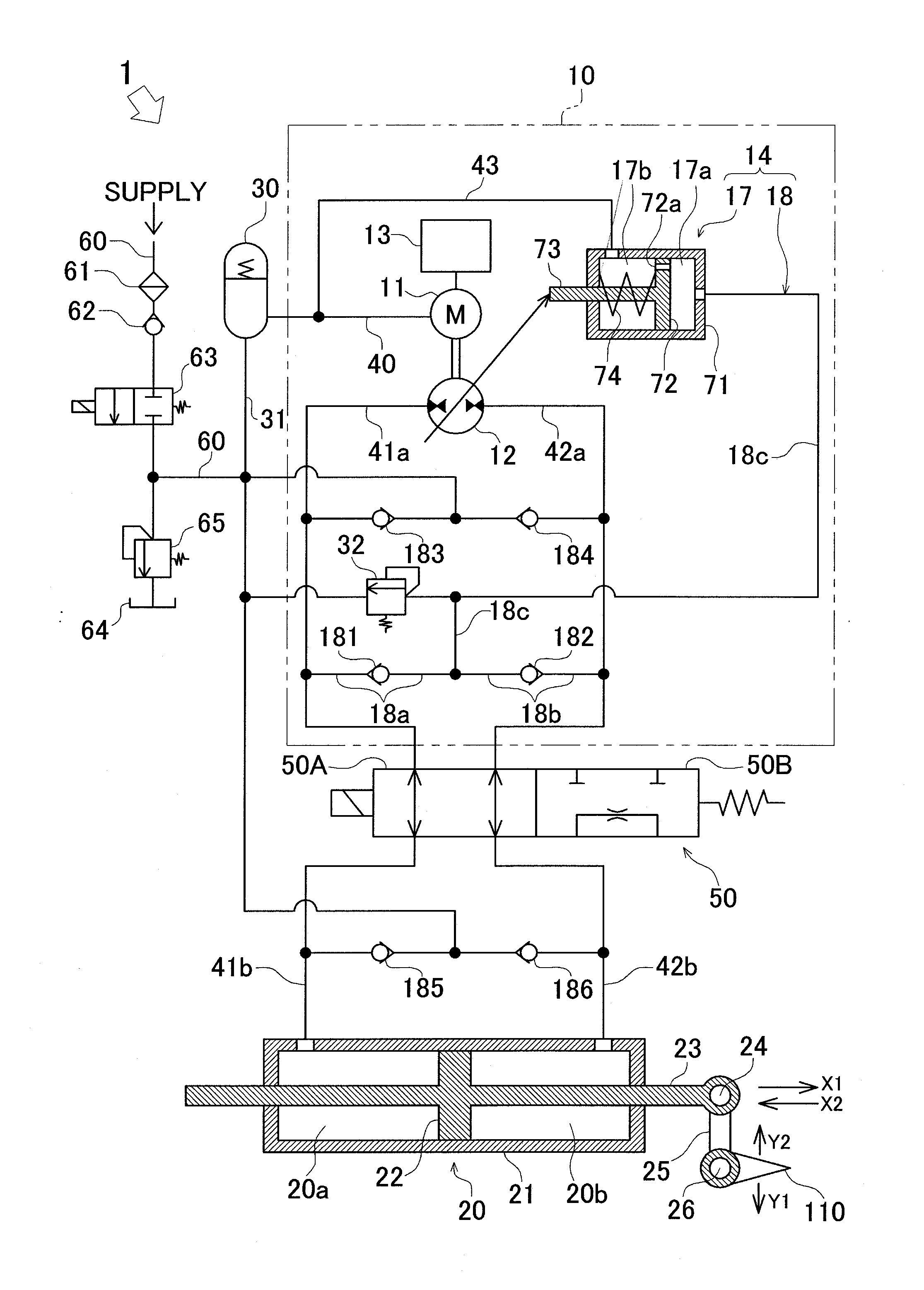
[0054]FIG. 1 illustrates a hydraulic circuit of an electric actuator of Embodiment 1, according to the present invention. In FIG. 1, an EHA (Electric Hydrostatic Actuator) 1 serving as an electric actuator includes: a hydraulic pressure supply device 10 (hydraulic fluid supply device) of the present embodiment according to the present invention; a hydraulic cylinder 20 serving as a hydraulic actuator, which is driven by the pressure of oil supplied from the hydraulic pressure supply device 10.

[0055]The hydraulic pressure supply device 10 includes: a servo motor 11 (adjustable-speed motor); a variable-volume pump 12 capable of outputting oil (hydraulic fluid) to two channels (oil passages 41a and 42a) according to the rotation of the servo motor 11; a motor control device 13 (electric motor control unit) which controls the servo motor 11 so as to achieve a set rotation speed; a...

embodiment 2

[0100]Next, the following describes an EHA 2 of Embodiment 2 according to the present invention. FIG. 6 illustrates the EHA 2 of Embodiment 2 according to the present invention. The EHA 2 (electric actuator) of Embodiment 2 is the same as the foregoing EHA 1 of Embodiment 1 except in the structure of the pump control device in the hydraulic pressure supply device. The members identical to those described in Embodiment 1 are given the same reference numerals and no further explanation for these members is provided hereinbelow.

[0101]A pump control device 200 of the EHA 2 includes: a spool valve 220 (pressure adjustment unit) between a variable-volume pump 12 and a tilt angle adjusting cylinder 17. That is, the pump control device 200 of Embodiment 2 includes: a tilt angle adjusting cylinder 17; an oil passage 230 which communicates oil passages 41a and 42a with the tilt angle adjusting cylinder 17; check valves 181 and 182 provided to the oil passage 230; and a spool valve 220. The oi...

embodiment 3

[0106]The following describes an EHA 3 of Embodiment 3. FIG. 7 illustrates the EHA 3 of Embodiment 3 according to the present invention. FIG. 8 shows a relation between an ejection pressure and ejection volume of a variable-volume pump illustrated in FIG. 7. The EHA 3 (electric actuator) of Embodiment 3 is the same as the EHA 2 of Embodiment 2 except in the structure of the pump control device of the hydraulic pressure supply device. Members identical to those of Embodiment 2 are given the same reference numerals, and no further explanation for those members is provided hereinbelow.

[0107]A pump control device 300 of the EHA 3 is provided with a switch valve 320 between a variable-volume pump 12 and the tilt angle adjusting cylinder 370. More specifically, the pump control device 300 of Embodiment 3 includes: a tilt angle adjusting cylinder 370; an oil passage 330 communicating oil passages 41a and 42a with the tilt angle adjusting cylinder 370; a check valves 181 and 182 provided to...


PUM


Abstract

An electric actuator of the present invention includes a hydraulic fluid supply device and an actuator actuated in response to an input of hydraulic fluid from a variable-volume pump. The hydraulic fluid supply device includes an adjustable-speed motor, the variable-volume pump which is driven by the adjustable-speed motor and ejects hydraulic fluid, an electric motor control unit which controls the adjustable-speed motor so as to achieve an intended rotation speed, and a pump control unit which controls the variable-volume pump so that the ejection volume of the variable-volume pump decreases with an increase in the ejection pressure of the variable-volume pump.

Description

CROSS REFERENCE TO RELATED APPLICATION[0001]The present application claims priority from Japanese Patent Application No. 2008-116716, which was filed on Apr. 28, 2008, the disclosure of which is herein incorporated by reference in its entirety.BACKGROUND OF THE INVENTION[0002]1. Technical Field[0003]The present invention relates to a hydraulic fluid supply device capable of supplying hydraulic fluid, and an electric actuator adopting such a hydraulic fluid supply device.[0004]2. Background Art[0005]There have been known an electric actuator such as one described in Japanese Unexamined Patent Publication No. 54604 / 2002 (Tokukai 2002-54604; hereinafter, Patent Citation 1), which adopts a hydraulic fluid supply device capable of supplying hydraulic fluid. This electric actuator has an electric motor, a pump which outputs oil according to the rotation of the electric motor, a cylinder into which the oil output from the pump is input, a controller which controls the rotation of the elect...

Claims


Application Information

Patent Timeline
Patent Type & Authority Applications(United States)
IPC IPC(8): B64C13/40F04B49/06
CPCF04B49/002F15B2211/20515F15B2211/27F15B2211/26F15B2211/20553
Inventor MAKINO, NAOHIRO
Owner NABLESCO CORP
Why Eureka
Try Eureka