
Hydraulic Engine

Active Publication Date: 2009-10-29
LANGHAM J MICHAEL
View PDF32 Cites 30 Cited by
  • Summary
  • Abstract
  • Description
  • Claims
  • Application Information

AI Technical Summary

Benefits of technology

[0011]The present inventor has recognized the desirability of an improved internal combustion engine having greater fuel-efficiency. The present inventor has further recognized that engine efficiency can be enhanced in any one or more of a variety of manners including, for example, by increasing the compression ratio (or alternatively, the “expansion ratio”) of an engine, by reducing engine fuel consumption when output power is not needed (e.g., when a vehicle is standing still), among others. The present inventor has additionally recognized the disadvantages associated with the use of various components of many conventional engines including, for example, crankshafts and associated components (e.g., connecting rods designed to link to crankshafts), camshafts and associated valve-train components (including, for example, timing chains, rocker arms, etc.), starters, flywheels, and various other engine components commonly employed in conventional internal combustion engines.
[0014]As a result of such characteristics, improved engines in accordance with such embodiments are able to achieve higher fuel efficiencies on any one or more of several counts. To begin with, such engines need not have any starter and / or flywheel, and consequently can be lighter than many conventional engines. Further, because the engines can be turned on and off repeatedly without any involvement by any starter and / or flywheel, the engines need not remain running when output power is not needed (e.g., when a vehicle within which the engine is operating is stopped at a stop light). Also, because of the particular piston arrangement, and particularly because the engines do not require any compression strokes involving the compression of fuel / air mixtures that could involve spontaneous pre-ignition, greater compression ratios (or “expansion ratios”) and correspondent fuel efficiency improvements are possible. Additionally, because compression strokes are not ever performed within the piston cylinders, no corresponding loss of rotational momentum and energy occurs as a result of such strokes.

Problems solved by technology

Although such conventional, crankshaft-based four stroke engines are popular and are undergoing continuing improvement, such engines nevertheless suffer from several limitations.
First, the fuel efficiencies that can be achieved by such engines continue to limited, something which is disadvantageous particularly insofar as the world's supply of fossil fuels is limited, insofar as demand (and consequently price) for fossil fuels continues to increase, and insofar as concerns over the impact of fossil fuel-based internal combustion engines upon the global environment continue to grow.
The fuel efficiencies of such engines are limited for a variety of reasons including, for example, the weight of such engines, and frequent operation of such engines in an idling manner when no load power is truly required (e.g., when an automobile is at a stop light).
A further factor that limits the fuel efficiencies of many such engines that employ spark plugs in combination with high octane fuels (rather than diesel engines) is that such engines, in order to avoid undesirable pre-ignition combustion events during the compression strokes of such engines, are restricted to designs with relatively modest (e.g., 9-to-1 or 10-to-1) compression ratios.
Second, because combustion strokes in such engines only occur during one of every four movements of a given piston, such engines by their nature require that an external input force / torque be applied to impart initial rotational momentum to the crankshaft of the engine in order for the engine to attain a steady state of operation in which the engine (and its crankshaft) is naturally able to advance to successive positions at which combustion events can take place.
Although such starter and flywheel components employed in conventional crankshaft-based four stroke internal combustion engines are commonly used, and well-understood in terms of their operation, the inclusion of such devices within such engines adds complexity and / or significant weight (as does a crankshaft) to the engine that, consequently, can increase the cost of designing or building the engine, increase the complexity of maintaining or repairing the engine, and / or further reduce the fuel-efficiency of the engine.
Further, depending upon how effective the starter of the engine is in terms of starting the engine, the need for a starter can further be an impediment to effective (and enjoyable) operation of the engine.
For example, it can be particularly frustrating to an operator when a starter mechanism fails or otherwise is incapable of starting an automobile engine in a short amount of time, particularly when the operating environment is cold such as during wintertime.
Various other types of internal combustion engines likewise suffer from various limitations that may be the same, similar to, or different from the limitations described above.
For example, while many of the above-described crankshaft-based 4 stroke internal combustion engines are able to run fairly cleanly in terms of their engine exhaust emissions, in contrast many diesel engines as well as conventional crankshaft-based 2 stroke engines under at least some operating circumstances are unable to effectively combust all of the fuel that is delivered into the cylinders of those engines and consequently emit fairly high levels of undesirable exhaust emissions.
This is problematic particularly as there continues to be increasing concern over environmental pollution, and various governmental entities are continuing to enact legislation and regulations tending to require that such engine exhaust emissions be restricted to various levels.
Yet even this type of engine can suffer from some of the same types of limitations described above.
In particular, such engines typically also are limited in their efficiency, and / or require additional components such as a starter and / or flywheel in order to allow the engine to begin running in a steady-state manner, and to continue running in such a manner.

Method used


Image

  • Hydraulic Engine
  • Hydraulic Engine
  • Hydraulic Engine

Examples


Embodiment Construction

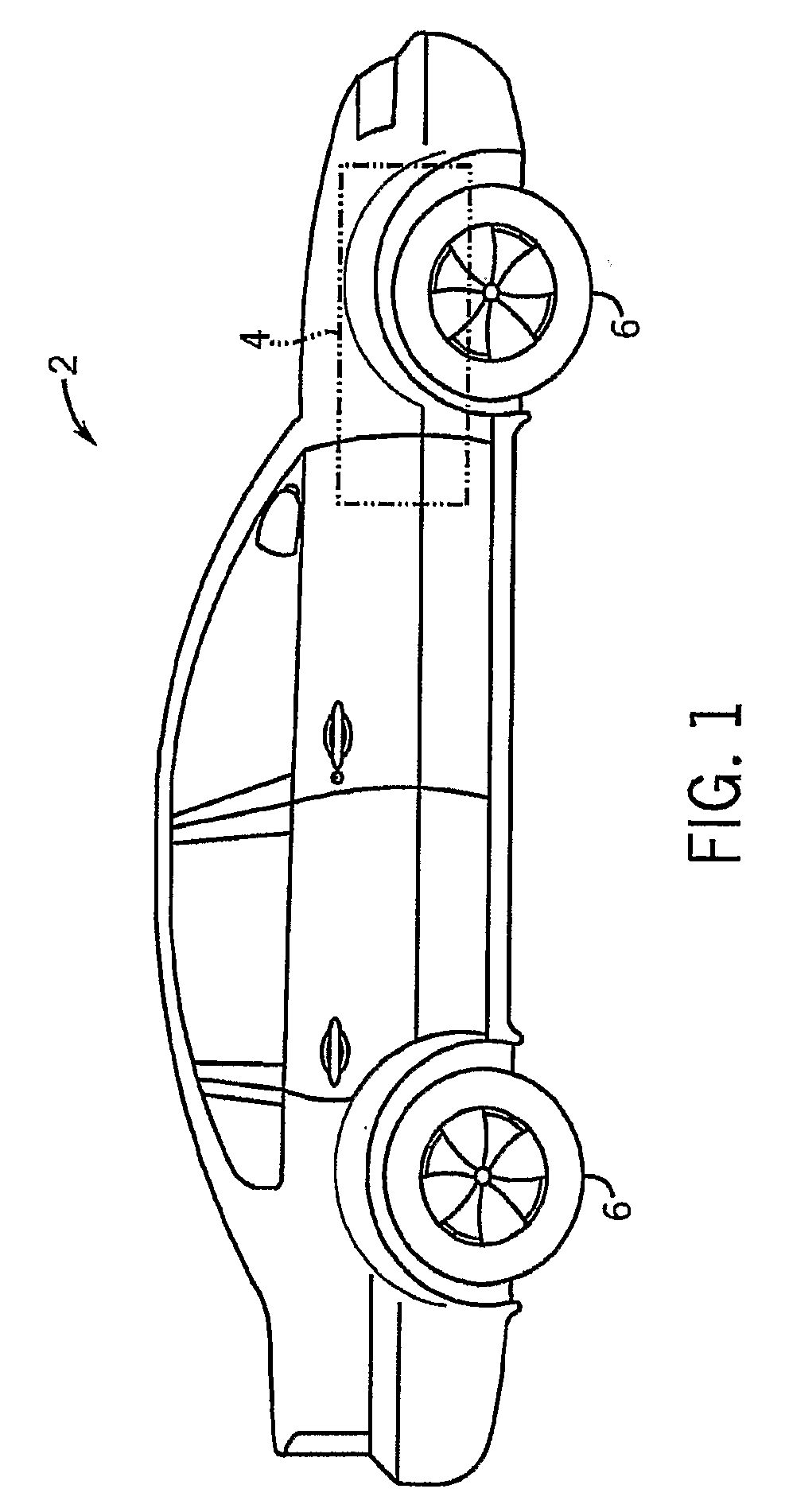
[0030]Referring to FIG. 1, an exemplary vehicle 2 is shown, within which can be implemented an engine 4 (shown in phantom) in accordance with one exemplary embodiment of the present invention. The vehicle 2 of FIG. 1, in particular, is shown to be an automobile capable of carrying one or more persons, including a driver, and having four wheels / tires 6 that support the vehicle relative to a road or other surface upon which the vehicle drives. Although FIG. 1 shows one exemplary vehicle, it should be understood that the present invention is applicable to a wide variety of different types of vehicles (e.g., automobiles, cars, trucks, motorcycles, all-terrain vehicles (ATVs), utility vehicles, boats, airplanes, hydrocraft, construction vehicles, farm vehicles, rideable lawnmowers, etc.), as well as other devices that do not necessarily transport people (e.g., walk-behind lawnmowers, snowblowers, pumping equipment, generators, etc.) that require or operate using one or more engines that ...


PUM


Abstract

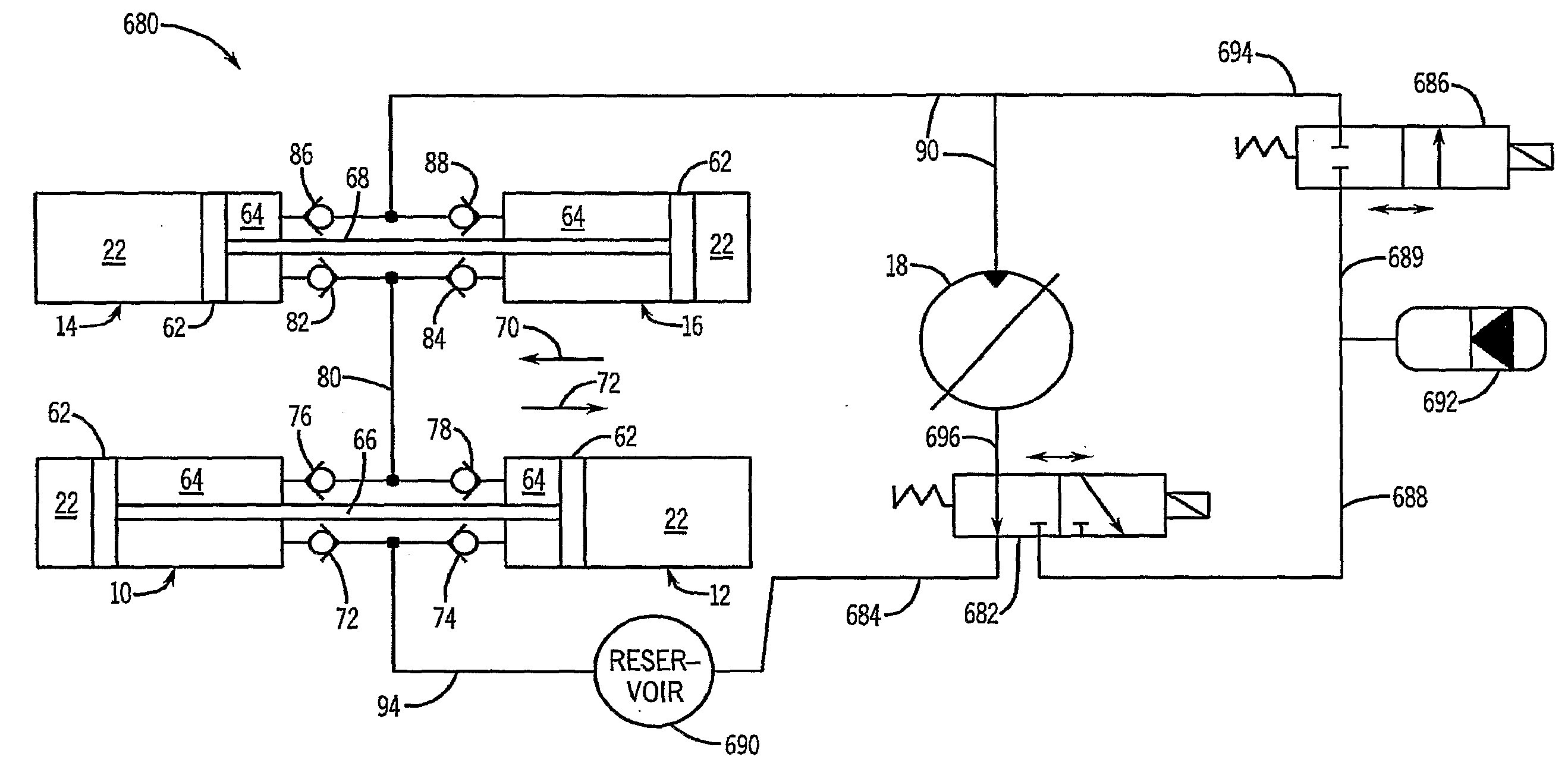
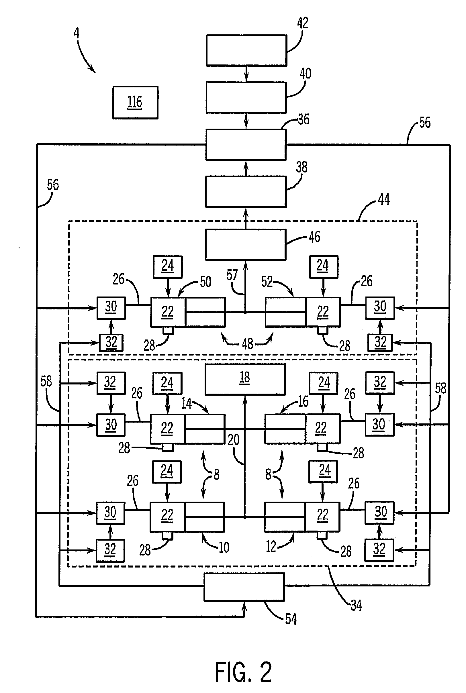
An internal combustion engine and method of operating such an engine are disclosed. In some embodiments, the engine includes a piston provided within a cylinder, wherein a combustion chamber is defined within the cylinder at least in part by a face of the piston, and an intake valve within the cylinder capable of allowing access to the combustion chamber. The engine further includes a source of compressed air, where the source is external of the cylinder and is coupled to the cylinder by way of the intake valve, and where the piston does not ever operate so as to compress therewithin an amount of uncombusted fuel / air mixture, whereby the engine is capable of operating without a starter. In further embodiments, the piston is rigidly coupled to another, oppositely-orientated second piston, and the two pistons move in unison in response to combustion events to drive hydraulic fluid to a hydraulic motor.

Description

CROSS-REFERENCE TO RELATED APPLICATIONS[0001]This application claims the benefit of U.S. provisional patent application No. 60 / 833,344 entitled “Linear Hydraulic Engine” filed on Jul. 26, 2006, which is hereby incorporated by reference herein.STATEMENT REGARDING FEDERALLY SPONSORED RESEARCH OR DEVELOPMENTField of the Invention[0002]The present invention relates to engines, and more particularly to internal combustion engines employing one or more pistons and cylinders, as can be employed in vehicles as well as in relation to a variety of other applications.BACKGROUND OF THE INVENTION[0003]Internal combustion engines are ubiquitous in the modern world and used for numerous applications. Internal combustion engines are the most common type of engine utilized for imparting motion to automobiles, propeller-driven aircraft, boats, and a variety of other types of vehicles, as well as a variety of types of motorized work vehicles ranging from agricultural equipment to lawn mowers to snow b...

Claims


Application Information

Patent Timeline
IPC IPC(8): F02D43/00F02M37/04F02B73/00F02P5/00
CPCF01B11/004F01L1/24F02B71/045F02B71/04
Inventor LANGHAM, J. MICHAEL
Owner LANGHAM J MICHAEL
Learn More