
Mat member, method for manufacturing the mat member, muffler and method for manufacturing the muffler

a technology of mat member and muffler, which is applied in the direction of machines/engines, packaging, textiles and paper, etc., can solve problems such as noise generation

Active Publication Date: 2009-11-05
IBIDEN CO LTD
View PDF9 Cites 33 Cited by
  • Summary
  • Abstract
  • Description
  • Claims
  • Application Information

AI Technical Summary

Benefits of technology

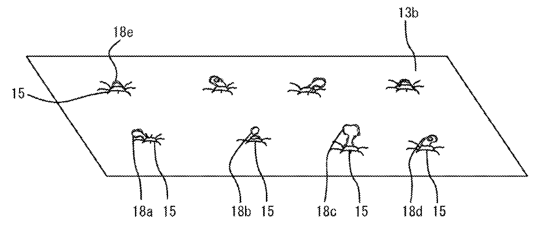
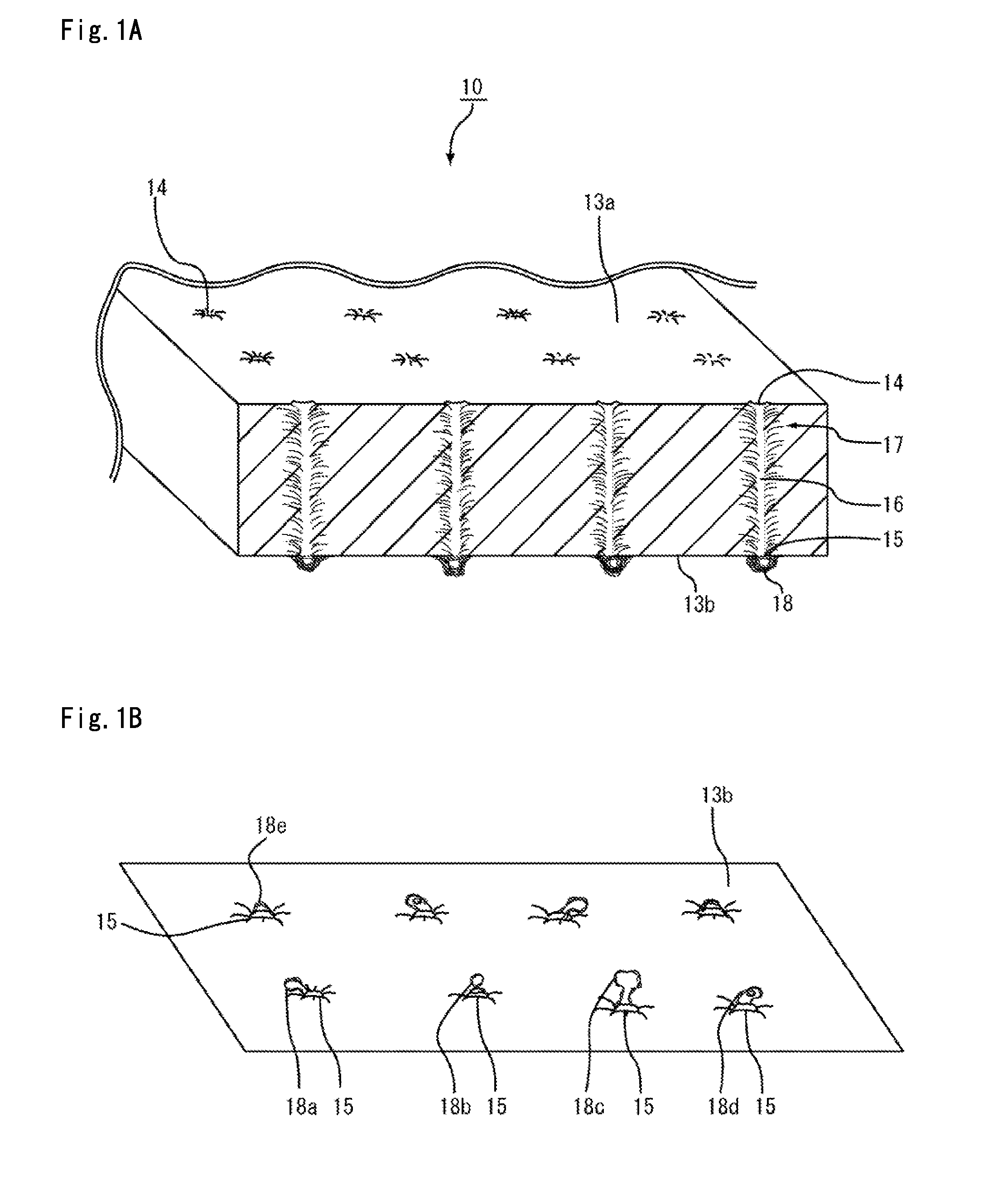
[0015]According to yet the other aspect of the present invention, a method for manufacturing a muffler includes providing a mat member. The mat member includes inorganic fibers, a first surface and a second surface opposite to the first surface. The first surface has a plurality of needle penetration marks and/or a plurality of needle protrusion marks. The second surface has a plurality of needle protrusion marks and/or a plurality of needle penetration marks. A plurality of needle marks are formed in the mat member by needle punching and extend from the needle penetration mark to the needle protrusion mark. An inorganic fiber bundle which includes a plurality of the inorganic fibers oriented in a closed loop configuration is formed at the needle protrusion mark. The mat member is wrapped around a side surface of an inner pipe having a plurality of small holes. The inner pipe wrapped with the mat member is press-fitted into an outer pipe to produce a press-fitted body in a manner that the inorganic fiber bundles contact an inner surface of the outer pipe. First and second end portion members are disposed to close first and second end openings of the outer pipe, respectively. The first and second end portion members are secured to the outer pipe.
[0016]According to yet another aspect of the present invention, a method for

Problems solved by technology

Conventionally, it has been known that, in an internal combustion engine of an automobile or the like, noise is generated when exhaust gases, generated by the internal combustion engine, are discharged outside through an exhaust path.

Method used


Image

  • Mat member, method for manufacturing the mat member, muffler and method for manufacturing the muffler
  • Mat member, method for manufacturing the mat member, muffler and method for manufacturing the muffler
  • Mat member, method for manufacturing the mat member, muffler and method for manufacturing the muffler

Examples


first embodiment

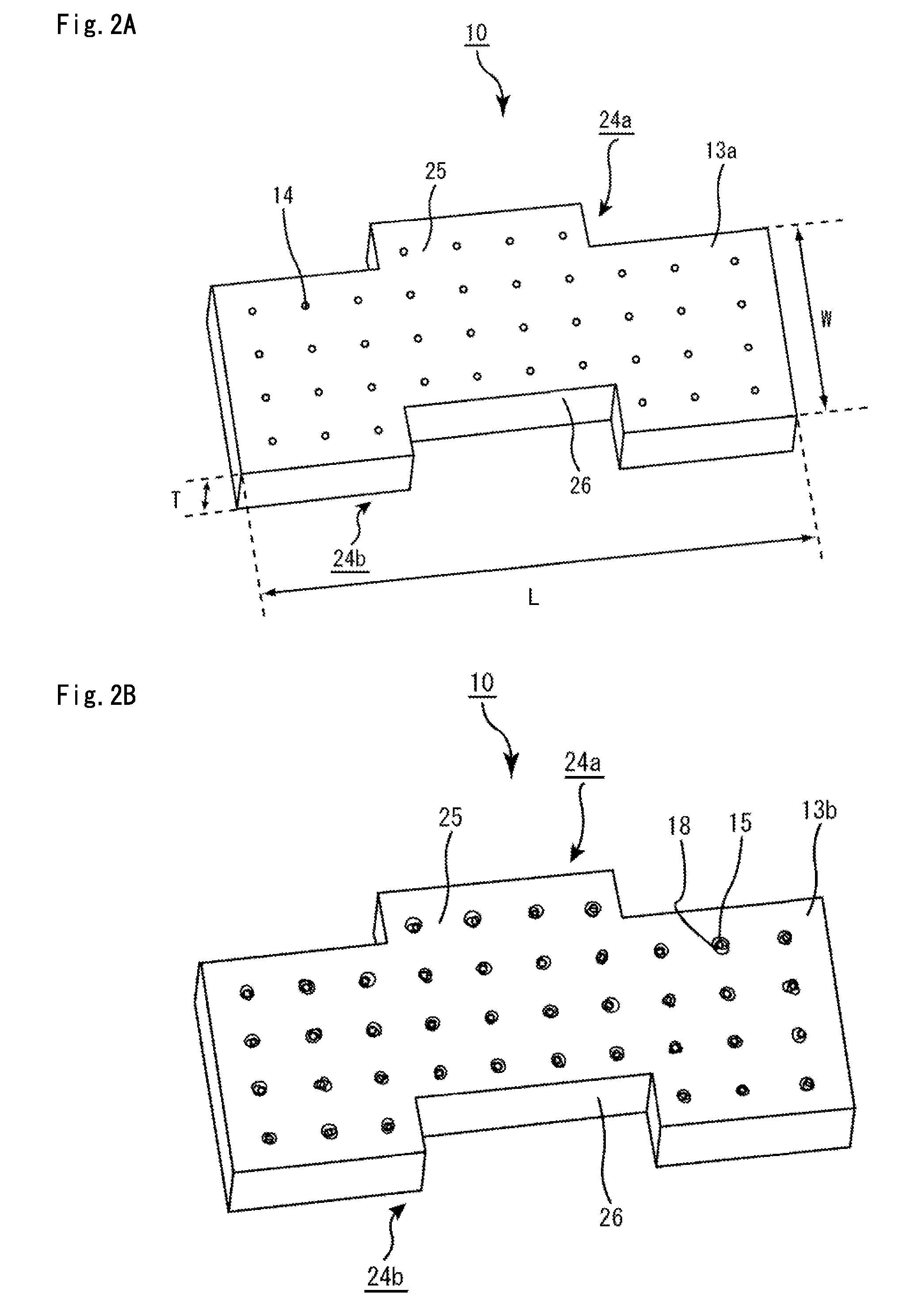
[0145]Referring to FIGS. 2A and 2B, FIG. 3, FIG. 4, and FIGS. 5A and 5B, the following description will discuss a first embodiment as one of the embodiments of the present invention.

[0146]FIG. 2A is a perspective view that schematically shows one example of a mat member of the present embodiment observed from one surface side, and FIG. 2B is a perspective view that schematically shows the mat member shown in FIG. 2A observed from the other surface side.

[0147]First, the structure of the mat member of the present embodiment will be explained.

[0148]A mat member 10 of the present embodiment is formed by including inorganic fibers mainly containing alumina and silica, that have an average fiber diameter of at least about 3 μm and at most about 10 μm. Here, as shown in FIGS. 2A and 2B, the outer shape of the mat member is a flat plate having predetermined length (indicated by an arrow L in FIG. 2A), width (indicated by an arrow W in FIG. 2A) and thickness (indicated by an arrow T in FIG. ...

example 1

1. Manufacturing of Mat Member

[0218]The mat member was manufactured by the following procedures.

(1-1) Spinning

[0219]To a basic aluminum chloride aqueous solution adjusted to have an Al content of 70 g / l and an atomic ratio of Al:Cl=1:1.8 was added silica sol in a manner that the inorganic fibers after firing was set to have a compound ratio of Al2O3:SiO2=72:28 (weight ratio). Thereafter, a proper amount of an organic polymer (polyvinyl alcohol) was further added thereto to prepare a mixed solution.

[0220]The resulting mixed solution was condensed to form a spinning mixture, and this spinning mixture was spun by using a blowing method so that an inorganic fiber precursor having an average fiber diameter of 5.1 μm was manufactured.

(1-2) Compression

[0221]The inorganic fiber precursor obtained in the above process (1-1) was compressed to manufacture a continuous sheet member.

(1-3) Needle Punching

[0222]Continuous needle punching was performed on the sheet member obtained in the above proc...

examples 2 , 3

Examples 2, 3 and Reference Examples 1, 2

[0256]A mat member and a muffler were manufactured in the same manner as in Example 1, except that, by altering the conditions for spinning the spinning mixture using the blowing method so as to set the average fiber diameter of the inorganic fibers forming the mat member in the process (1-1) of example 1 to the values as shown in Table 1, an inorganic fiber precursor having substantially the same average fiber diameter as the value shown in Table 1 was manufactured.


PUM

PropertyMeasurementUnit
Diameteraaaaaaaaaa
Diameteraaaaaaaaaa
Densityaaaaaaaaaa

Abstract

A mat member includes inorganic fibers, a first surface and a second surface opposite to the first surface. The first surface has a plurality of needle penetration marks and / or a plurality of needle protrusion marks. The second surface has a plurality of needle protrusion marks and / or a plurality of needle penetration marks. A plurality of needle marks are formed in the mat member by needle punching and extend from the needle penetration mark to the needle protrusion mark. An inorganic fiber bundle which includes a plurality of the inorganic fibers oriented in a closed loop configuration is formed at the needle protrusion mark.

Description

CROSS REFERENCE TO RELATED APPLICATIONS[0001]The present application claims priority under 35 U.S.C. §119 to PCT Application No. PCT / JP2008 / 058288 filed on Apr. 30, 2008, the contents of which are incorporated herein by reference in their entirety.BACKGROUND OF THE INVENTION[0002]1. Field of the Invention[0003]The present invention relates to a mat member, a method for manufacturing the mat member, a muffler, and a method for manufacturing the muffler.[0004]2. Discussion of the Background Art[0005]Conventionally, it has been known that, in an internal combustion engine of an automobile or the like, noise is generated when exhaust gases, generated by the internal combustion engine, are discharged outside through an exhaust path.[0006]Therefore, in order to reduce the noise, various mufflers to be installed in the exhaust path have been proposed.[0007]In particular, in order to reduce noise in a high frequency range, a muffler including a mat member formed by inorganic fibers and the ...

Claims


Application Information

Patent Timeline
IPC IPC(8): F01N1/14B32B3/10B05D3/12F01N1/24B21D51/16B28B1/00B32B38/00D04H1/4209D04H1/4218D04H1/46D04H1/488F01N13/16
CPCD04H1/4209D04H1/4218D04H1/46D04H1/488Y10T29/49398F01N3/2853F01N2310/02Y10T156/1033Y10T428/24281F01N1/04Y10T442/682Y10T442/687Y02A50/20F01N1/24F01N13/16
Inventor OKABE, TAKAHIKOSUZUKI, DAISUKE
Owner IBIDEN CO LTD
Learn More