Mass spectrometer

a mass spectrometer and mass spectrometer technology, applied in the field of mass spectrometers, can solve the problems of increasing the number of times of such operations, requiring a considerable long period of time, and requiring a large amount of time to repeat such operations, and achieve the effect of high mass resolution

Inactive Publication Date: 2009-11-05
SHIMADZU CORP +1
View PDF3 Cites 44 Cited by
  • Summary
  • Abstract
  • Description
  • Claims
  • Application Information

AI Technical Summary

Benefits of technology

[0032]In a mass spectrometer using a two-dimensional array detector consisting of an in-situ storage image sensor or similar detector capable of repeatedly acquiring images at high rates yet for only a limited number of frames,

Problems solved by technology

Repeating such operations requires a considerably long period of time if the mass analysis needs to be performed over a two-dimensional region with a certain area.
This situation is undesirable not only because the analysis time becomes long, but because the biological sample may be damaged or degraded during the long period of time, causing the analysis to be rather inaccurate.
Unfortunately, this method is costly since arranging a plurality of conventional ion detectors in a two-dimensional pattern requires providing as many measurement circuits (amplifiers, digitizers and so on) in parallel.
On the other hand, decreasing the number of ion detectors for cost reduction deteriorates the positional (or spatial) resolution of the system, making the method rather impractical.
Altho

Method used


Image

  • Mass spectrometer
  • Mass spectrometer
  • Mass spectrometer

Examples


first embodiment

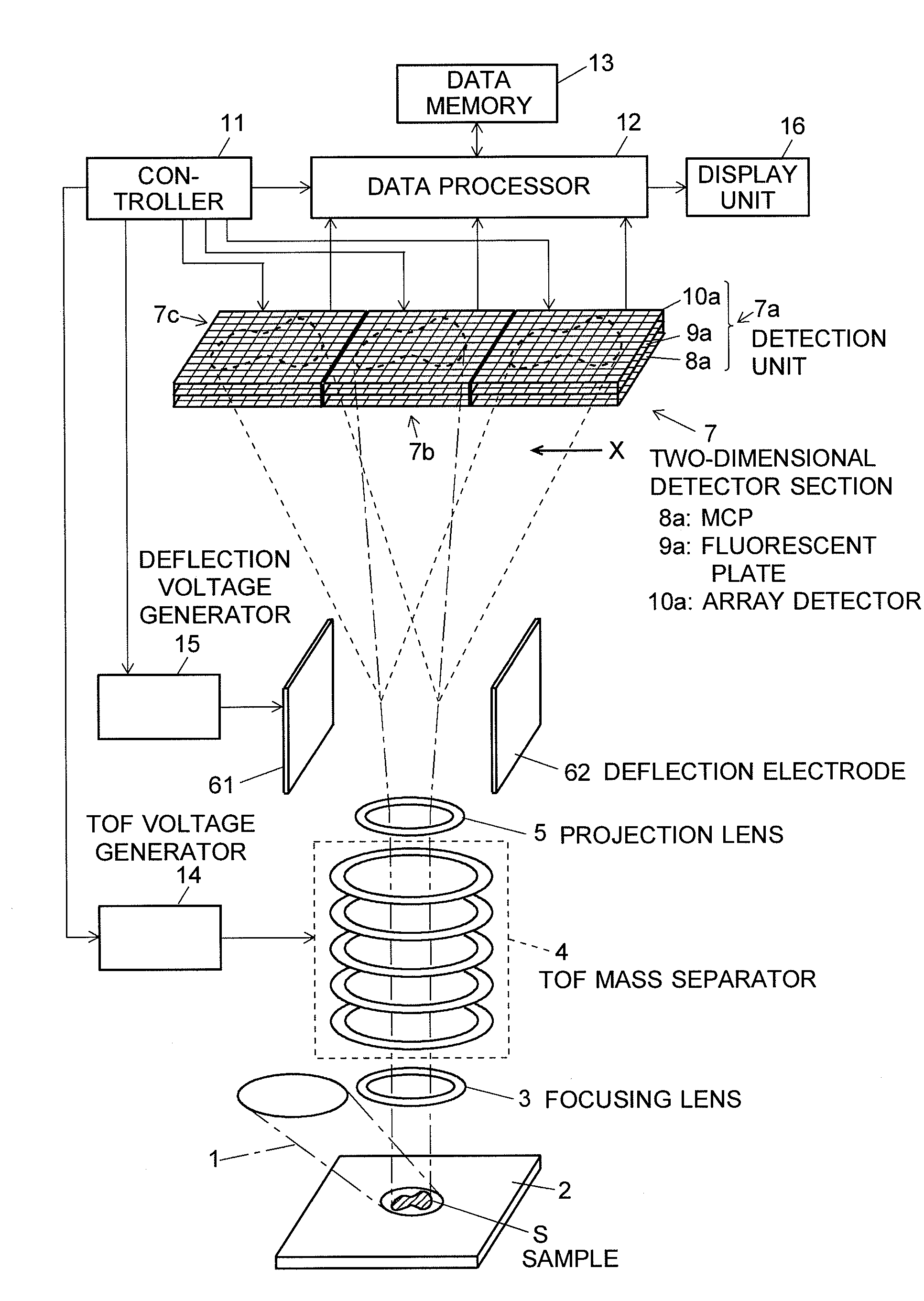
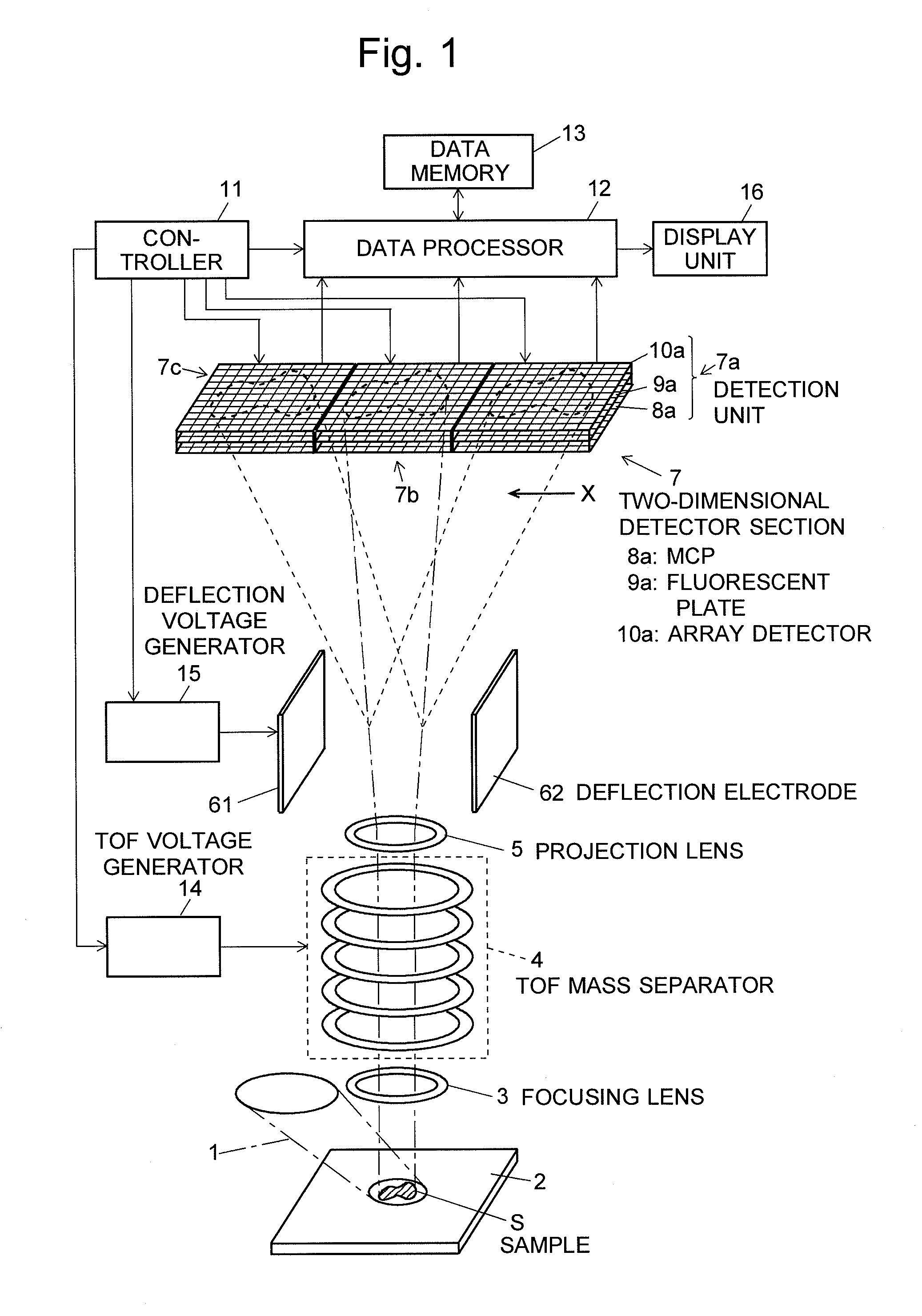
[0044]A mass microscope, which is one (first) embodiment of the mass spectrometer according to the present invention, is hereinafter described with reference to the drawings. FIG. 1 is a configuration diagram of the essential portions of the mass microscope in the first embodiment.

[0045]This mass microscope employs a laser desorption ionization (LDI) method in order to simultaneously ionize all the components contained in a sample. In this method, a sample S placed on a sample stage 2 is irradiated for a short period of time with a two-dimensionally spread ray of ionization laser light 1. The irradiation of the sample S with the laser light 1 causes various substances present within a two-dimensional area on the sample to be almost simultaneously ionized. Thus, various ions are generated in a two-dimensionally distributed form. These ions are then introduced through a focusing lens 3 into a time-of-flight (TOF) mass separator 4 while maintaining the relative positional relationship ...

second embodiment

[0066]Another (second) embodiment of the present invention is hereinafter described with reference to FIG. 8. FIG. 8 is a configuration diagram of the essential portions of the mass microscope in the second embodiment. The components identical to those of the first embodiment are denoted by the same numerals, and explanations of these components are omitted. The blocks representing the configuration of the electrical circuits of the control system or processing system are also omitted to simplify the figure.

[0067]The configuration of the second embodiment includes another pair of deflection electrodes 301 and 302 facing each other in the direction perpendicular to the previously mentioned parallel deflection electrodes 61 and 62. The nine detection units 7a, 7b, 7c, 7d, 7e, 7f, 7g, 7h and 7i are arrayed not only along the X-axis but also along the Y-axis. In this configuration, the flight path of the ions is deflected in the X-direction by a deflection electric field created by the ...

third embodiment

[0068]Another (third) embodiment of the present invention is described with reference to FIG. 9. FIG. 9 is a configuration diagram of the essential portions of the mass microscope in the third embodiment. The components identical to those of the first embodiment are denoted by the same numerals, and explanations of these components are omitted. The blocks representing the configuration of the electrical circuits of the control system or processing system are also omitted to simplify the figure.

[0069]Unlike the first and second embodiments in which an electric field was used to deflect ions, the third embodiment uses a magnetic field to deflect ions. Specifically, a pair of parallel plate magnetic poles 311 and 312 are disposed in place of the deflection electrodes in the space between the projection lens 5 and the two-dimensional detector section 7. A static magnetic field is created between these parallel plate magnetic poles 31. In general, an ion being accelerated by a voltage E ...


PUM


Abstract

A sample S is irradiated with a two-dimensionally spread ray of laser light to simultaneously ionize substances within a two-dimensional area on the sample. The resultant ions are mass-separated by a TOF mass separator 4 without changing the interrelationship of the emission points of the ions. The separated ions are then directed to a two-dimensional detector section 7 through a deflection electric field created by deflection electrodes 61 and 62. The two-dimensional detector section 7 consists of a plurality of detection units 7a arranged in parallel, each unit including an MCP8a, fluorescent plate 9a and two-dimensional array detector 10a. The magnitude of deflecting the flight path of the ions by the deflection electric field is changed in a stepwise manner with the lapse of time from the generation of the ions so that a plurality of mass analysis images are sequentially projected on each detection unit 7. When the mass analysis image shifts from one detection unit to another, the data acquisition operation by the two-dimensional array detector in the previous detection unit is discontinued. As a result, a predetermined number of the latest images are held inside the detector. Thus, the measurement time can be extended to widen the measurable mass-to-charge ratio range, while ensuring a high mass resolution.

Description

TECHNICAL FIELD[0001]The present invention relates to a mass spectrometer for ionizing one or more substances present within a two-dimensional area on a sample, and then performing a mass analysis of the ionized substances. The mass spectrometer according to the present invention is particularly suitable for a mass microscope, which is the combination of a microscope for microscopically observing a two-dimensional area on a sample and a mass spectrometer for performing a mass analysis of the substances present on the observed area to obtain two-dimensional information concerning their qualities and / or quantities.BACKGROUND ART[0002]Mass spectrometers are an apparatus for ionizing molecules and atoms of a component included in a gaseous, liquid or solid sample and separating the ions according to their mass-to-charge ratio to detect them in order to identify the component or determine its content. These days, it is widely used for various purposes such as the determination of biologi...

Claims


Application Information

Patent Timeline
IPC IPC(8): H01J49/00
CPCH01J49/061H01J49/0004
Inventor OGAWA, KIYOSHIETOH, TAKEHARU
Owner SHIMADZU CORP
Why Eureka
Try Eureka